

Introduction: Arduino Binary Clock Using LED Matrix


This site has many fine posts describing construction of binary clocks. I am terrifically shaky, however, and have difficulty with any soldering. I therefore wanted to make mine from an 8x8 MAX7219-controlled LED matrix.
Step 1: Reading the BCD Binary Clock
A great explanation can be found here: http://www.wikihow.com/Read-a-Binary-Clock.
The clock described uses the binary coded decimal (bcd) display method, described first. Each digit of the time, in this method, is isolated and displayed as a binary number. 37 Minutes, for instance, is displayed as 0000 0011 (3 in binary) in one column and 0000 0100 (7 in binary).
Each digit of each segment--hours, minutes, seconds--occupies one column. With a blank column separating each column pair, 8 columns are used. Don't things work out neatly, sometimes?
Step 2: Equipment Needed
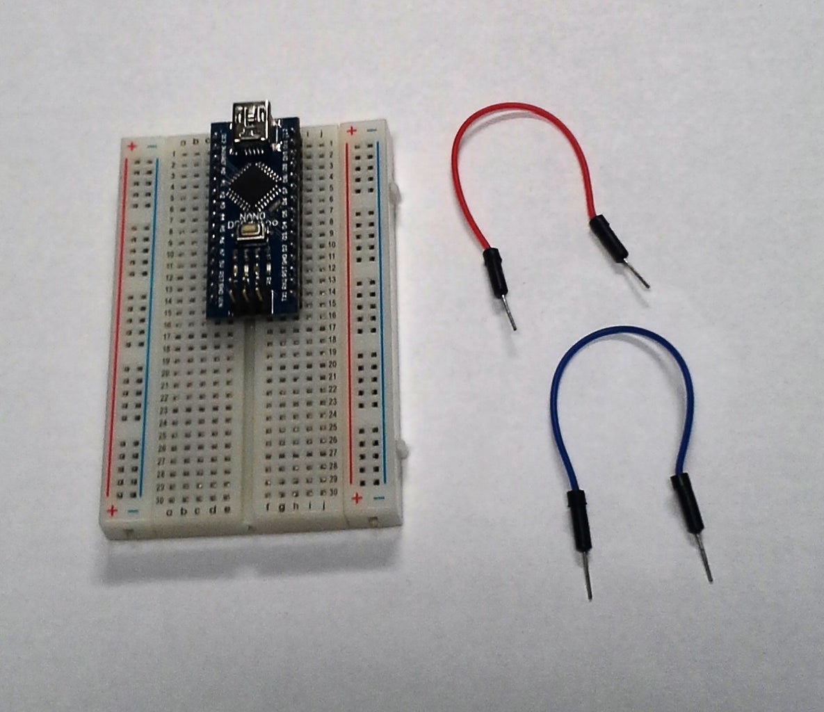
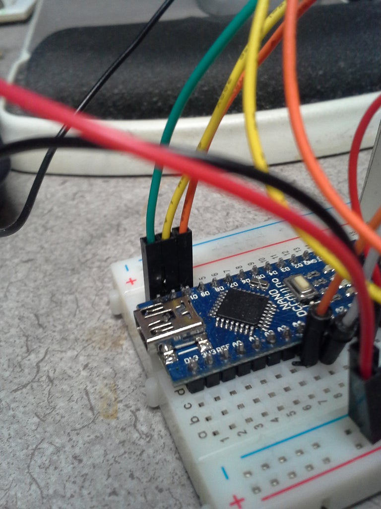
Arduino.
I used a Nano, as I can put everything on one breadboard. I purchased an off-brand one.
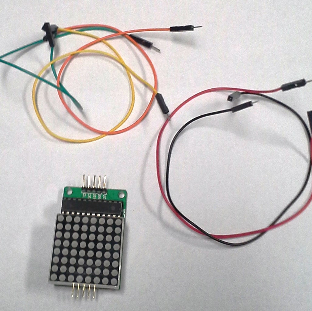
Display
- One MAX 72xx LED matrix breakout board. Note that MAX72xx pins may vary from model to model, so check).
- Power, ground, three signal jumpers for it.
- I mounted mine upside-down, and therefore use male-female jumpers to its control pins.
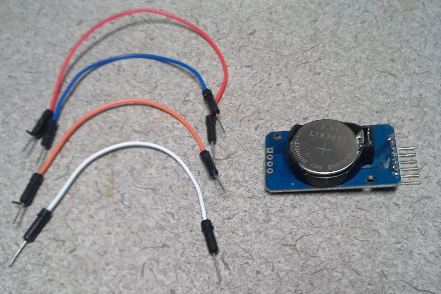
I2C DS3231 Real Time Clock (RTC) breakout board.
- Power, ground, two signal wires.
Small breadboard.
I crowded everything onto a 400-pin board.
Batteries or AC adapter for the Arduino (not shown).
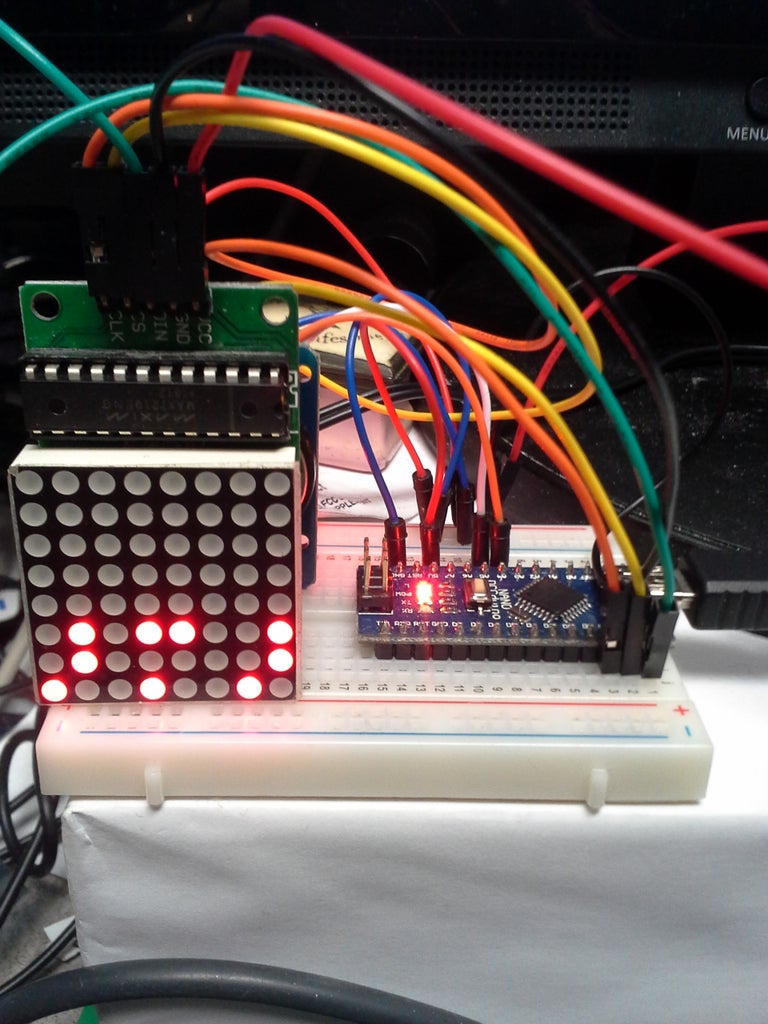
Step 3: Wiring
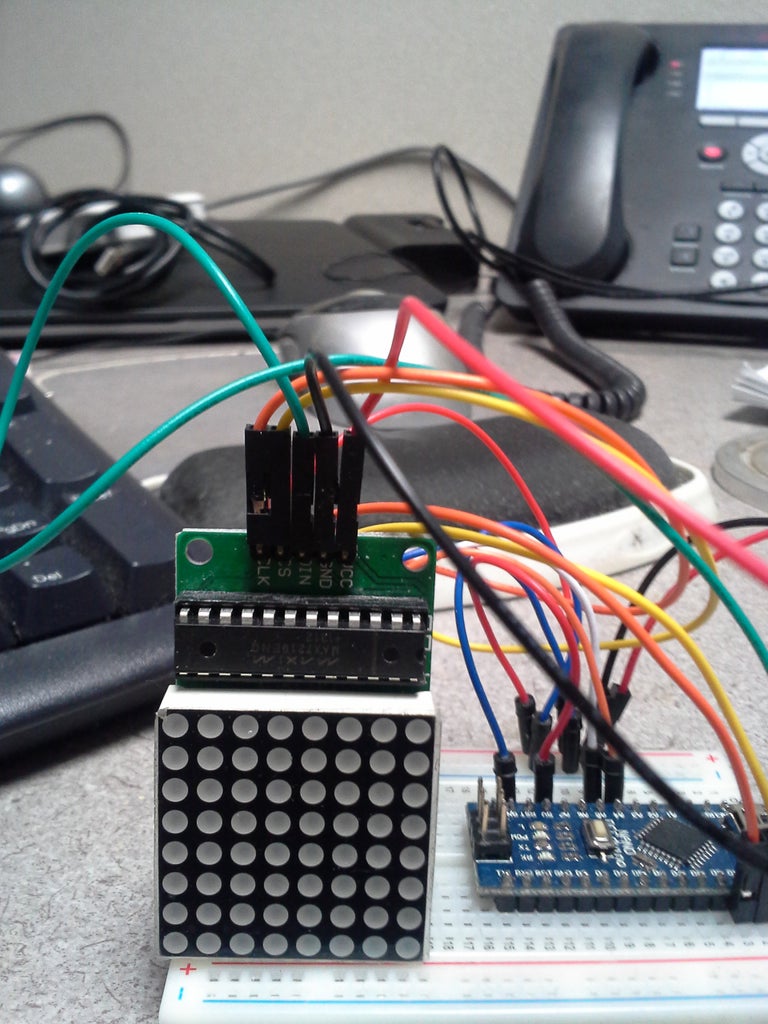
The MAX72xx's five pins are wired according to the ledControl library page. My 7219's pin order is different from that described; double-check yours.
- VCC--+5V
- GND--Ground
- DIN (Data in)--D10
- CS (Referred to as "LOAD" in the library.)--D11
- CLK (Clock)--D12
The clock is connected to the I2C pins (check your Arduino model). These are, for the Nano...
- VCC--+5V
- GND--Ground
- SDA--Analog 4
- SCL--Analog 5
Step 4: Notes on the Algorithm
Each column of the LED matrix indicates one digit. Separating. the hours, minutes, and seconds into two single digits is trivial...
- Isolate the first digit by integer-dividing the hours by 10 (no remainder).
- Get the second with module division (remainder only) by 10.
We illuminate a column's LED(s) to correspond to the appropriate digit's binary representation. To do so, we use the ledcontrol.h library's setRow() function requiring three arguments--
- Matrix number (the library handles up to 8 per instance). Count begins at 0, and that's the number used in this sketch, as we have only one matrix.
- Column number (counting from the left, numbered 0-7). As used, columns 0 and 1 correspond to the hour's first and second digits, respectively.
- Byte that describes, top to bottom, the LEDs to turn on (1=on).
The hour/minute/second single digits are returned as decimal integer values (i.e. 0-9). They must be converted to ("cast" as, in programming parlance) the required byte (binary) values using the byte() function.
SetRow(), on my matrix, fills LEDs in line with the input/output pins, but the least significant bit ("bottom") is closer to the output pins--I'd call it mounted upside down. (Try it with your own matrix LED). Note that you'd need to invert the order by bitwise math in order to mount your LED matrix right-side up, and use the SetColumn function if you want to mount it sideways.
Step 5: The Sketch
Attachments

Step 6: Improvements and Comments
After building in and seeing it in action, I find the display disappointingly petite, a function, of course, of the LED matrix size.
I have a desk clock, and will pull out the motor housing, replacing the clock face with a circle of smoked glass or acrylic, if I can find one cheaply enough. (I will try stopping by my local auto window tinting place and asking for scraps). The LED matrix's circuit board and chip would consequently be hidden from view. Another possibility is to cut a wood circle stained or painted to a nice contrast, and cut a square hole in it for the LED face to poke through. I doubt my scroll saw skills, however, so I'd need to fake up some sort of bezel. Brass face, perhaps? I can produce a smooth finish on a lathe or a lovely swirly pattern with a fly cutter, end mill, or lapping compound, but would need to figure out a way to get relatively square corners in the led hole, impossible with an end mill--maybe a slitting saw.
At the moment, time is adjusted by reprogramming the Arduino Nano, impractical at best. Three pushbuttons can be added, one for each segment--hours, minutes, seconds--and the appropriate button's press would increment the current segment by one unit. That's the simplest to program. One button will be more elegant, though: long press to get into hours adjustment mode, short press increments, and so on.
I'd like to transfer the sketch to an ATTiny85 and reclaim my Nano board (also easier to transfer to a clock case).
Suggestions and comments are, of course, always welcome.


