Introduction: Arduino Biped


A robot is defined as a mechanical or virtual intelligent agent that can perform tasks automatically or with guidance .
Typically a robot is an electro -mechanical device that is guided by computer and electronic programming .
So I decided to try my hand at robotics, and what appealed to me the most was the Biped as it involves movement and balance. For this Ide be able to incorporate servos and accelerometers.
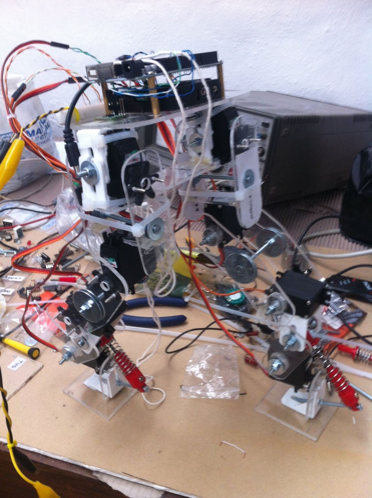
The Final Biped is a two legged Arduino controlled actuated robot with 8 Degrees of Freedom (DOF) and accelerometer feedback.
This is my first time using Arduino, servos and accelerometers so this may not be the best way to go about the final robot but it seems to be working as intended.
Supplies:
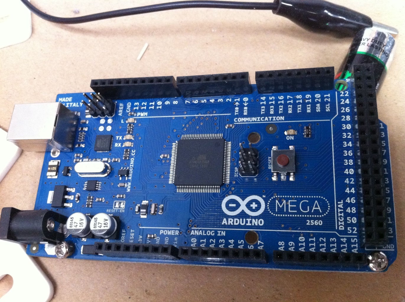
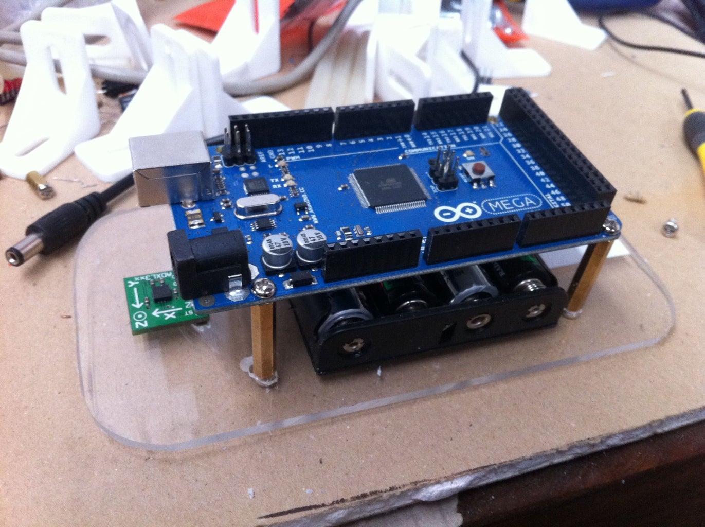
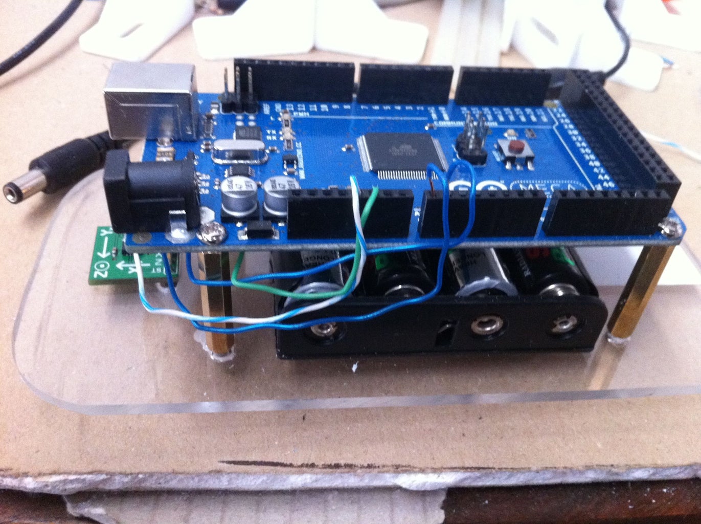
After much research I decided to go with the Arduino as it has Servo libraries which makes life a lot easier. Instead of creating 8 different PWM (pulse width modulation) signals for each servo, one can just set the rotation using a single command. (I will post code later). The Arduino I went with is the MEGA250 which has 14 PWM pins , Im only using 8 for the servos, also more than enough Analogue inputs for the accelerometer.
The Arduino does not come with an istallation cd so the software can be found at the following link:
Arduino Software
It also doesn't come with the USB cable.
You will have to install the Arduino drivers, they come with the download. A "how to" google search should help.
The servos I used are HD-1501MG which have the minimum torque I would suggest for a biped of this size as it struggles in some positions. I purchased 8 from microRobotics. Heres the link to the product, you can also view the specs:
SERVOS
As far as precision is concerned, these are probably not the best option, but anything more high end was too expensive considering I needed 8.
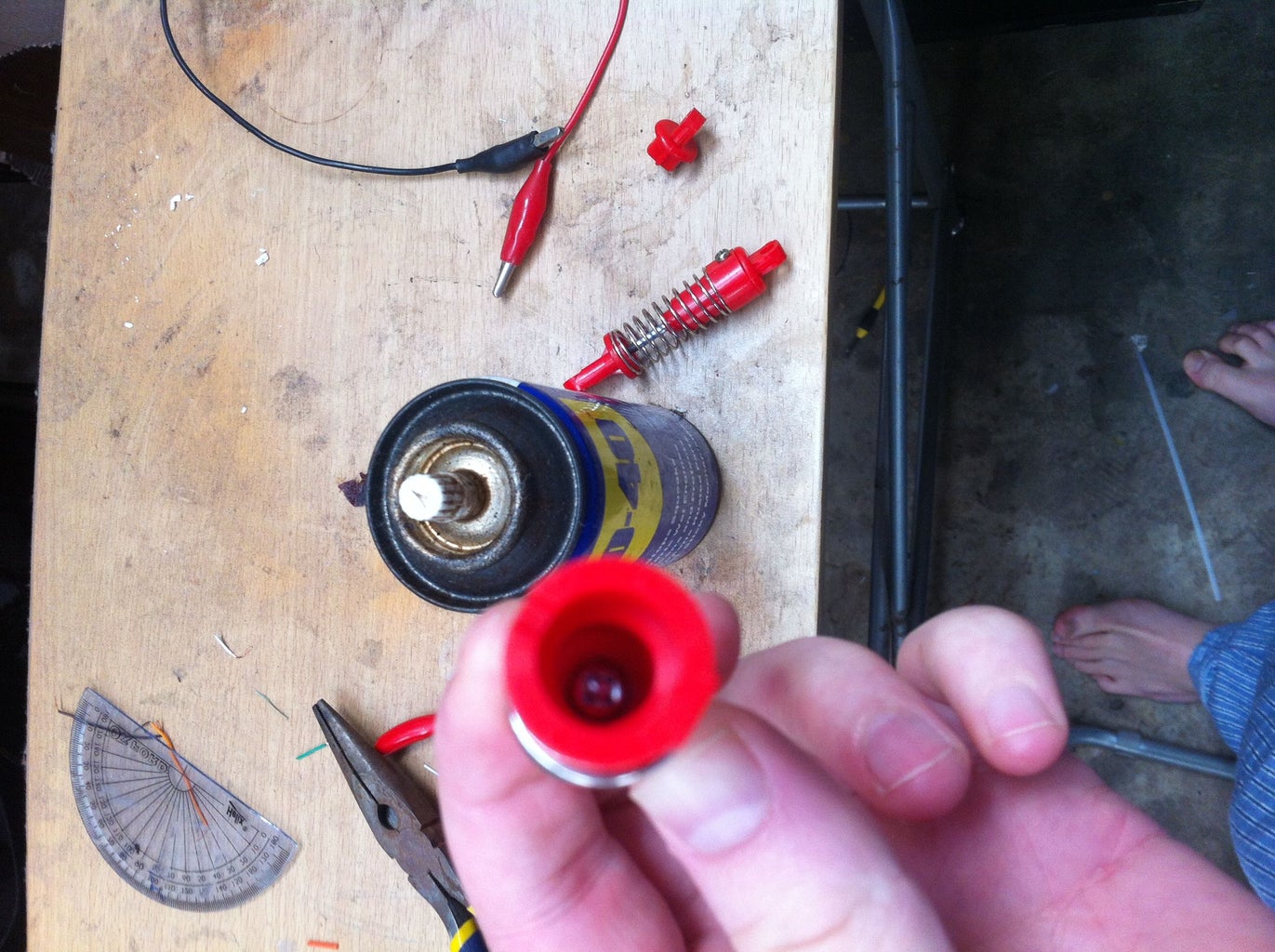
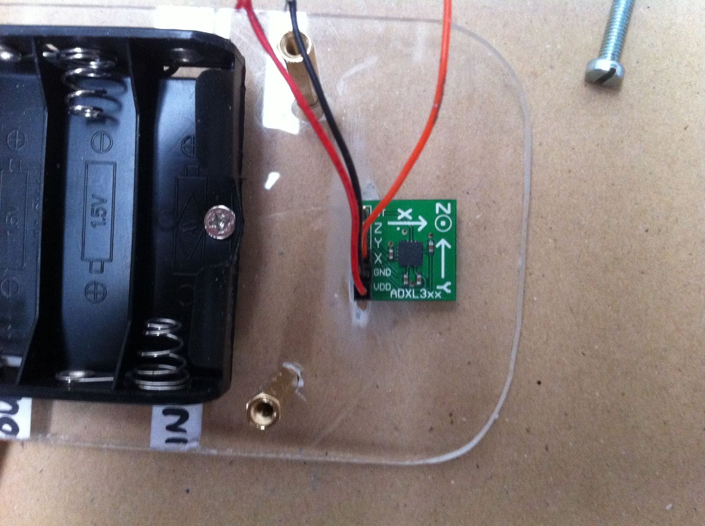
The accelerometre is an ADXL330 which I picked up off an old project. A gyroscope from a broken WII remote works well too.
The structure of the BOT is Perspex, I cut it from a single sheet and rounded the edges.
I used many nuts and bolts, and a glue gun to hold it together.
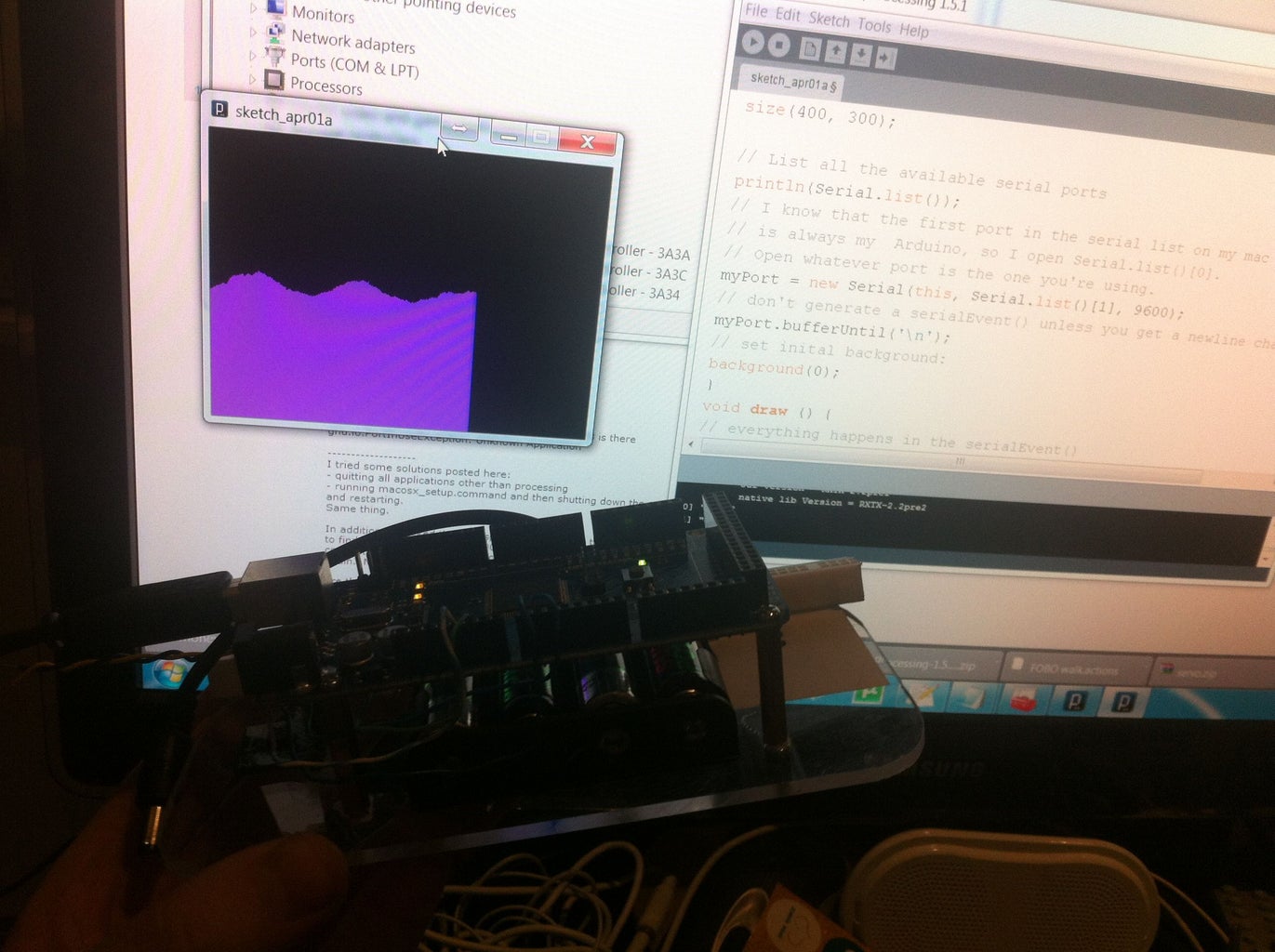
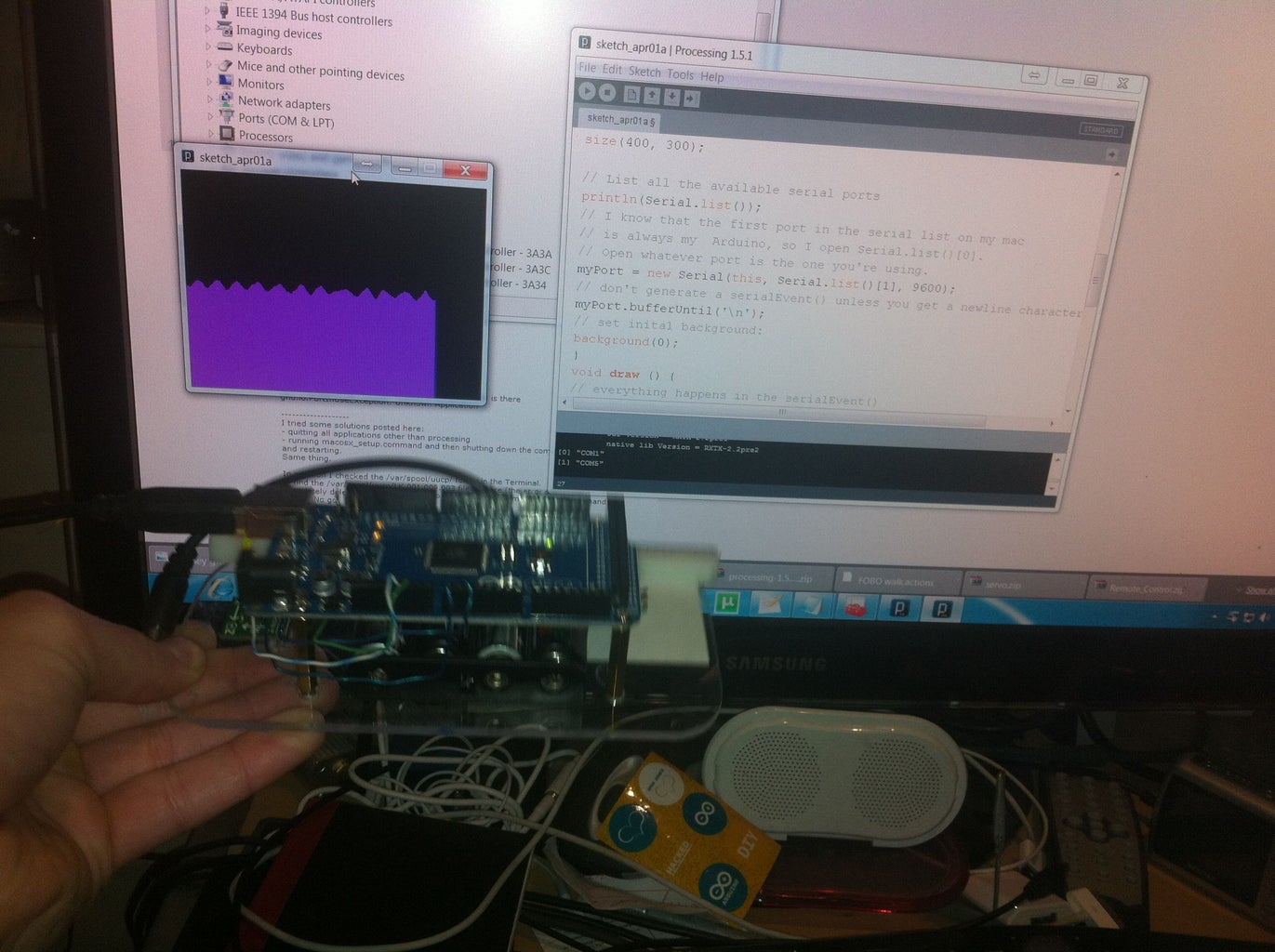
An example of a biped with serial communication, Also has a nice GUI which I adapted to work with mine:
http://www.projectbiped.com/prototypes/fobo
A similar Project, which I used the code as a template for my code:
http://lars.roland.bz/biped-arduino-robot/
A nice tutorial on how to get the robot walking:
https://www.youtube.com/watch?v=Xhz6m6fu494
Step 1: Structure - Perspex

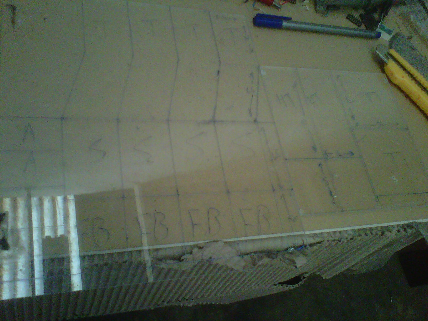


Cutting the Perspex:
- I used a Table saw for the long cuts and a jig saw for the short ones.
- I used a grinder to round the edges.
- I used a Table saw for the long cuts and a jig saw for the short ones.
- I used a grinder to round the edges.
Step 2: Feet


Feet Construction:
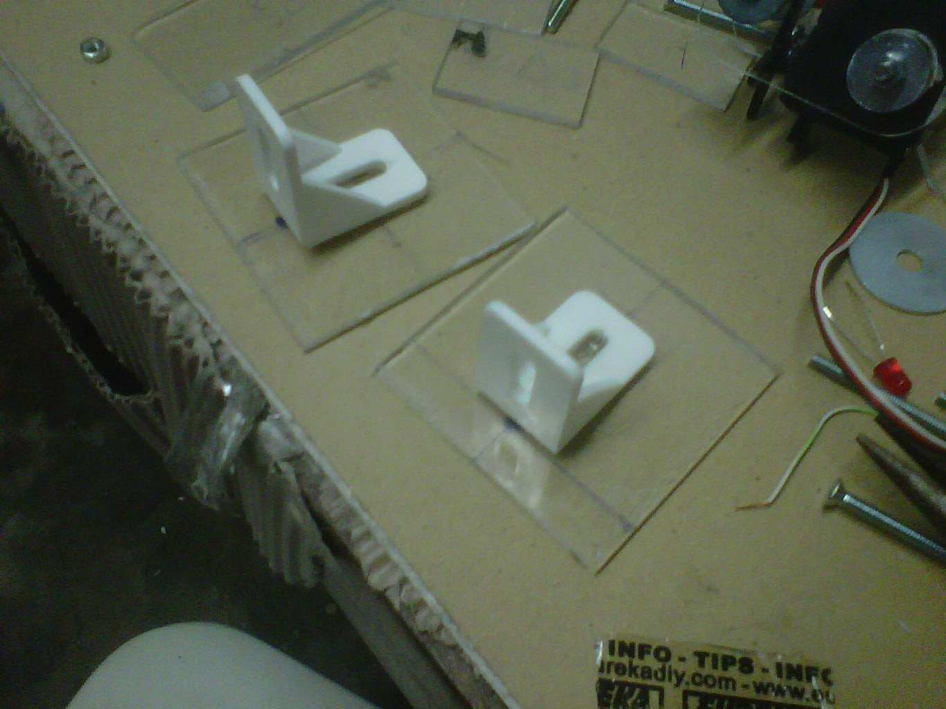
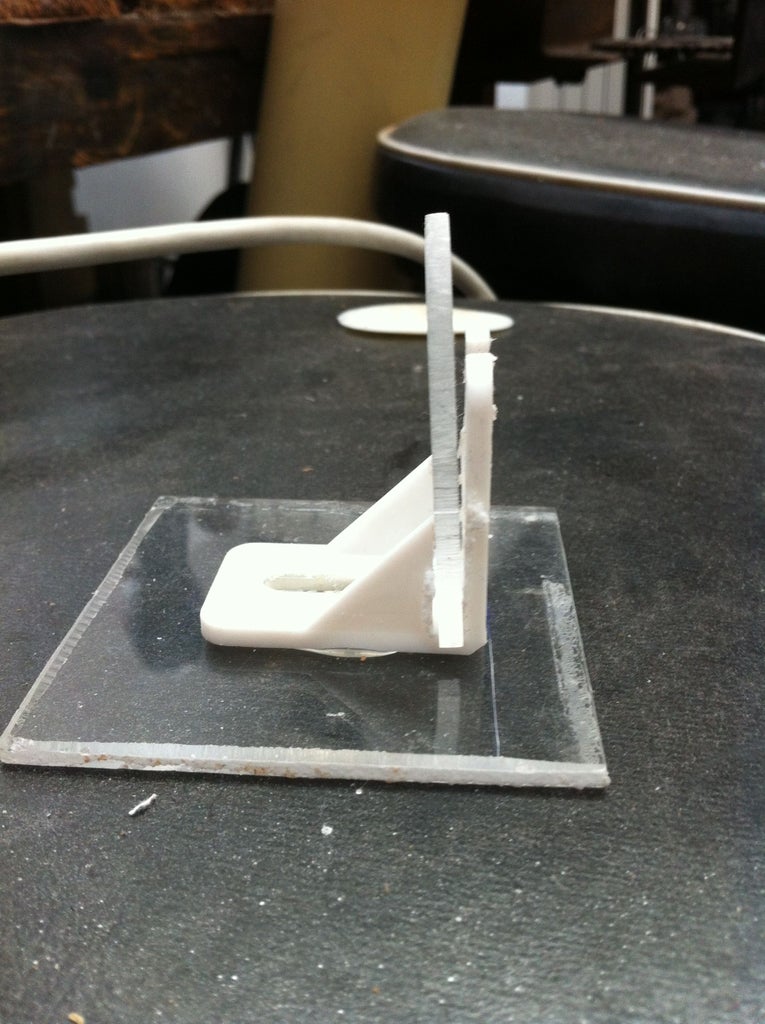
- Attach a single bracket onto the center of the base of the foot. img[1]
the ankle servo will be supported by this bracket
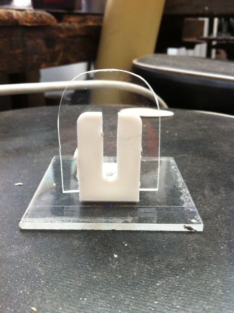
- Cut a slot in the bracket for a perspex piece which we will mount to the servo. img[2]
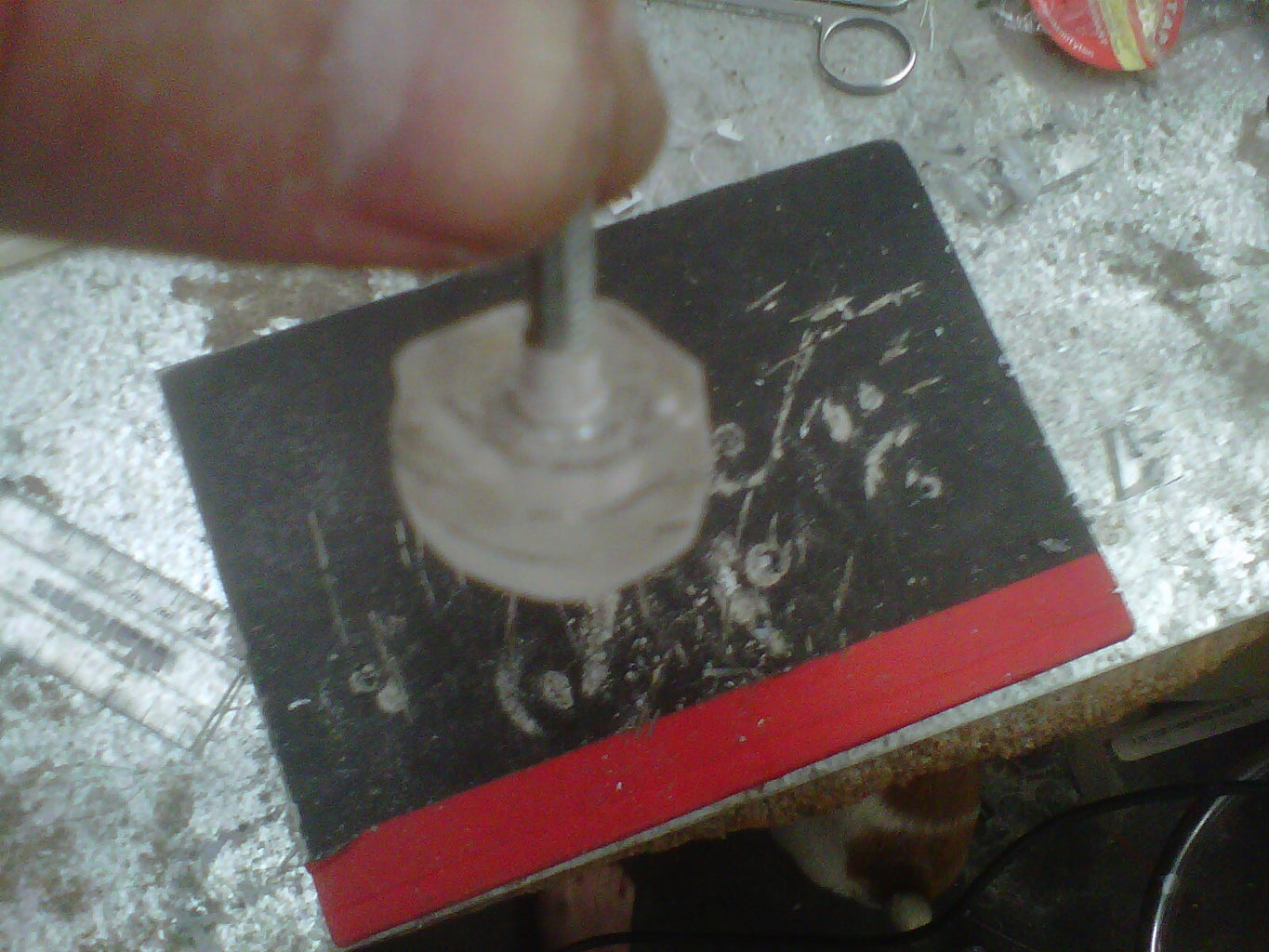
- place the perspex piece into the slot and glue down with the glue gun. img[3]
- Round off the edges. img[4]
- Attach a single bracket onto the center of the base of the foot. img[1]
the ankle servo will be supported by this bracket
- Cut a slot in the bracket for a perspex piece which we will mount to the servo. img[2]
- place the perspex piece into the slot and glue down with the glue gun. img[3]
- Round off the edges. img[4]
Step 3: Joints


The Pivot points are made up of 3 small square pieces of perspex sandwidged together.
- The first square has a hole drilled in so that the bolt can fit through, but the head cant.
- The second square has a larger diameter hole that the head of the bold can fit through freely
- The third square is solid piece of perspex which goes on top of the 2nd square to make sure the bold doesnt fall out.
Put the bolt through the hole of the1st square, place the 2nd square over the head of the bolt (note: the perspex needs to be slightly thicker than the height of the bolts head). Place the 3rd over the 2nd to cover the bolts head.
- grind down the edges of the block
The joint is complete, I used about 14 of these.
Step 4: Lower Legs - (tibia/fibula)


The best way to do this step is to follow the pictures below as it is hard to explain the attachments.
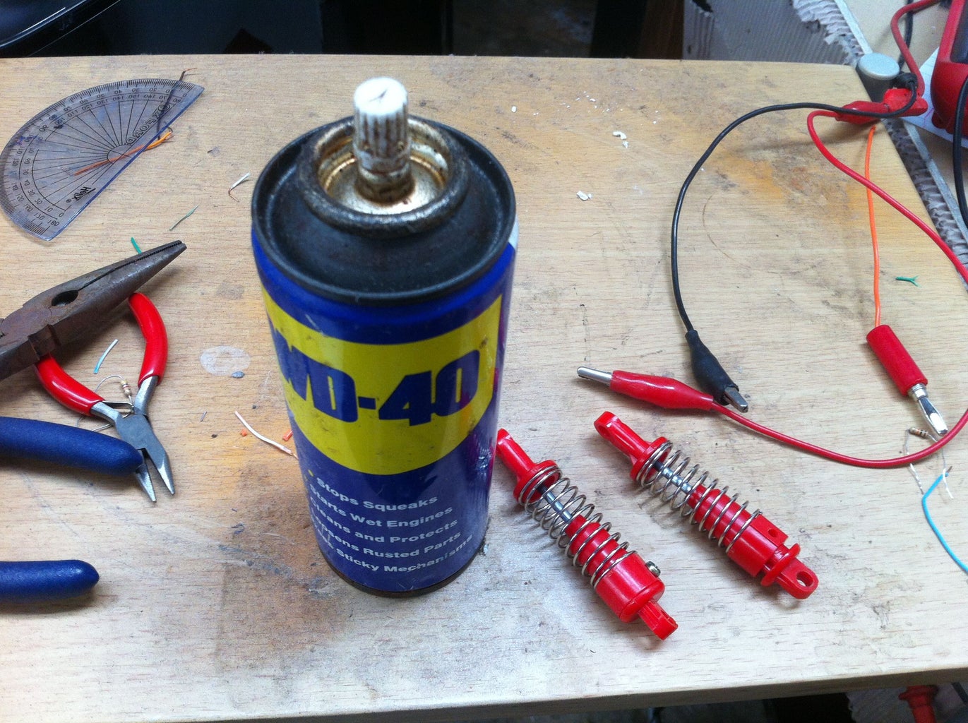
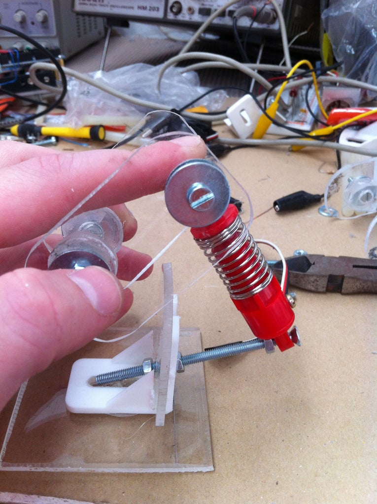
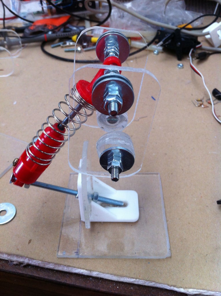
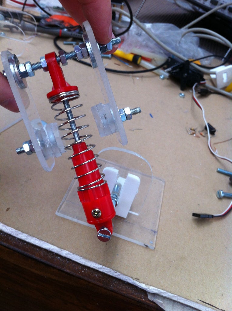
Basically the lower leg consists of the Foot---> Bolt---->Shock Absorber---->cross bolt of shin
- To fit the lower bolt holding the shock absorber, drill a hole at a 45 degree angle through the lowest part of the perspex front plate of the foot.
- Slip on the shock absorber to the end and then slip a nut on each side to hold it in place,
- see pictures on how to assemble the shin region.
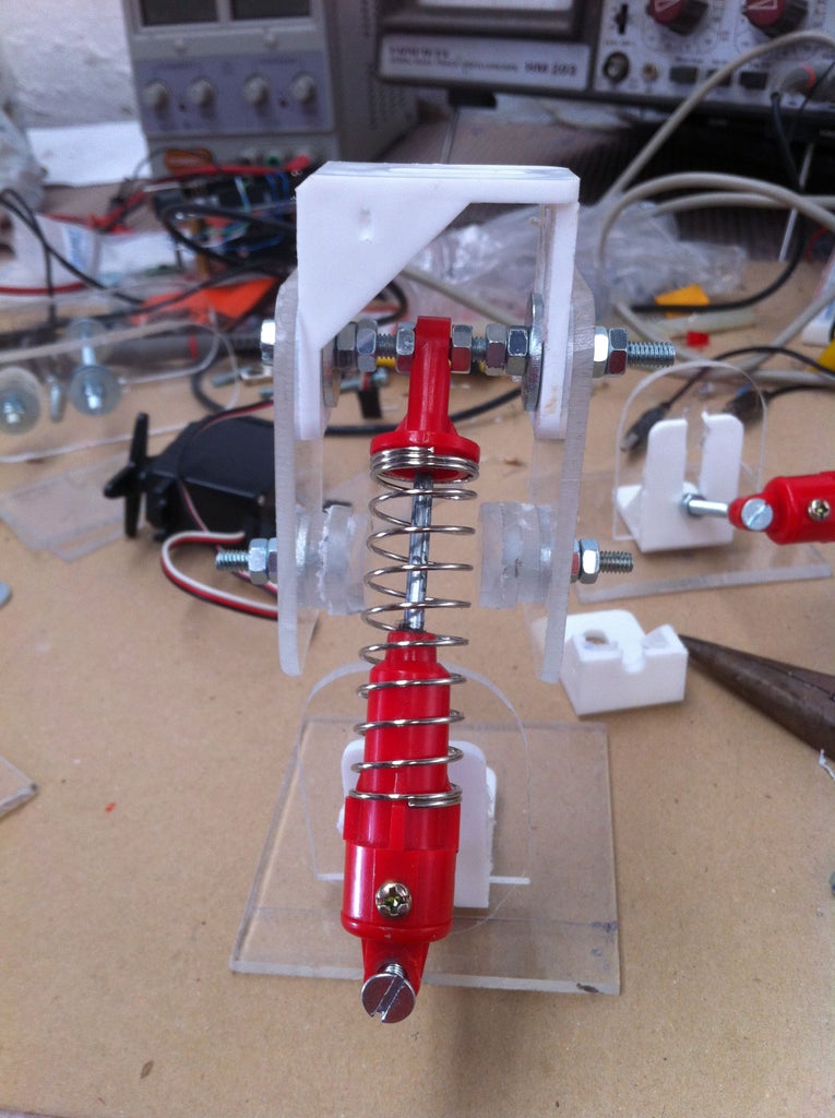
I added a wider base to the feet and a back support with a pivot point all for extra stabilization, see last image.
Basically the lower leg consists of the Foot---> Bolt---->Shock Absorber---->cross bolt of shin
- To fit the lower bolt holding the shock absorber, drill a hole at a 45 degree angle through the lowest part of the perspex front plate of the foot.
- Slip on the shock absorber to the end and then slip a nut on each side to hold it in place,
- see pictures on how to assemble the shin region.
I added a wider base to the feet and a back support with a pivot point all for extra stabilization, see last image.
Step 5: Thighs -(Femoral Region)


The thighs are setup by bolting two of the "thigh" perspex cutouts together. Once the edges of the cutouts are rounded off, make sure to drill holes for the pivot points, 1 at either end of a single side of a thigh section at the centre of the radius of the rounded edge.
- Drill the holes for the servos.
- When attaching the servos, make sure to position them so that their is enough rotation space in the correct direction.
- the best way to attach the servo is to drill 3 holes in line, the 2 holes on either side will attach the turning arm/disk, the center hole will be so that you can attach the servo to its arm/disk with its bolt after attaching the disk to the perspex.
- Now attach the thigh to the lower leg.
Step 6: Hip - (Gluteal Region)


The Hip region is made the same way as the thighs, except they are facing forward instead of sideways.
Step 7: Waist


Step 8: Final Steps