

Introduction: Arduino Car Display


I built an on-board diagnostics (OBD-II) based display using a 7" TFT LCD from Adafruit, a Teensy 3.6, the Freematics OBD-II I2C Adapter, and some cheep backup sensors I found on Amazon. The display has two pages: one for when my Honda Accord is in drive and one for when it is in reverse.
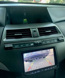
When my car is in drive, the RPM, MPH, engine load percentage, battery voltage, cabin temperature, and engine coolant temperature are displayed (there are several other vehicle statistics available to display if one does not want these).
When my car is in reverse, the Arduino IDE compatible Teensy 3.6 reads an animated bitmap image of my car I found online, displays it, and then reads the backup sensors. The four sensors each have their distance in feet plus an animation behind the car that changes color based off of how close the object is to the car (just green means < 5 feet, green and yellow means < 2.6 feet, and green, yellow, and red means < 1 foot).
Finally, I added the capability to dim the display at night.
The end result looks great and functions very well in my car. I even ended up installing it in the center console, which was a whole other process that I won't get into in this instructable. The list of parts that I used to create this LCD display are below.
1) UPDATE: I2C version is no longer sold - Must purchase UART version: https://freematics.com/store/index.php?route=product/product&product_id=83 - $59.98
-This means Arduino code written for I2C version will need to be modified
2) Backup Sensors - $15
3) 7" TFT LCD Display - $38
4) SPI based LCD Display Driver - $35
5) Teensy 3.6 - $30
6) Level Shifter - $4
7) 74HC125 Tri State Buffer IC -$6 for 2 pack (I'm sure you could find this cheeper elsewhere)
8) MicroSD Card >= 1 GB - $4
9) Wire, capacitors, and resistors.
10) LP3470-2.93 Power on Reset IC - $2
11) (optional): DS18B20 Temperature Sensor - $8
12) (optional): OBD-II Splitter - $10
13) (optional): Add a circuit fuse cord - $8 for pack of 5
Step 1: Reading the Backup Sensors


This step is tricky because these backup sensors communicate to a transceiver and then to a small LCD as seen in the picture above. I wanted a way to get rid of their display and use my own. With the help of a website I found after some googling (Hacking reverse parking sensors), I was able to read the proprietary communication protocol that the transceiver sends to the LCD screen. For some reason, the communication protocol is not a typical one such as I2C, UART, CAN, USB, etc. and the protocol differs depending on the supplier. I highly recommend that you purchase the set I linked above if you are going to use my code because it was specifically written for those sensors.
Before disconnecting the LCD they provided, I probed the three wires joining the transceiver and the LCD. There was +5V red wire, ground black wire, and a blue wire. After hooking up my oscilloscope to the blue wire and ground, I saw a trace similar to the picture seen above but not exactly (I used the picture from the website linked above). My trace had a HIGH longer duration start bit, followed by 17 more shorter duration bits. The bits 0-5 after the start bit did not have useful information. Bits 6-8 correspond to sensor A, B, C, or D. Bits 9-16 corresponded to the length in meters. I included an Arduino IDE sketch that reads the sensors and outputs the data over the serial console.
Step 2: Creating the Bitmap Image and Putting It on a MicroSD Card


I used a free photo editing software called GIMP to crop and resize an image of my car from the top view. I then exported the image as a 24 bit bitmap image named "car.bmp" that is 110 pixels by 250 pixels. I uploaded this to a microSD card and put the microSD card in my Teensy 3.6 microcontroller.
The main reasons I went with the Teensy 3.6 instead of an UNO was the speed at which the Teensy could read an SD card and display the image using the RA8875 display driver. Using an UNO, the process took about 8 seconds, while a Teensy 3.6 took 1.8 seconds.
Step 3: Connecting the Hardware

Adafruit has a really good looking 7" TFT LCD that is driven by an IC called the RA8875. I chose this display and display driver for two reasons. First, there are extensive libraries prewritten for the display. Second, the display driver can talk to any microcontroller over SPI, meaning there aren't that many wires connecting the microcontroller to the RA8875.
There are two downsides to this setup. First is the fact that there is a hardware bug with the RA8875 board from Adafruit requiring the use of the 74HC125 tri-state buffer IC if you want to use any SPI based device such as a SD card. To more fully understand the hardware bug, please read the following forum. Second, is the relatively long amount of time it takes for images to be sent to the LCD. Also, the long amount of time it takes for an image to be sent to the LCD is due to the SPI connection, which is limited by the microntrollers' clock speed and the large amount of data that has to be sent to the display driver over very few wires.
I created a Fritzing schematic so that anyone that would like to create this display can easily read what pins on the Teensy 3.6 connect to. I included a .frz file below. The only two components that aren't labeled are the capacitors, which are a 1F 16V electrolytic capacitor and a 100μF ceramic capacitor. I included these to make sure the power to the Teensy microcontroller was steady DC +5V and did not contain any voltage spikes (may not be necessary but I included them because a car's voltage supply can fluctuate quickly depending on the load on the battery).
A few things to mention about the components. First, the level shifter takes any 5V signal and turns it into a 3.3V Teensy 3.6 safe voltage. This is necessary for the OBD I2C adapter as well as the backup sensor transceiver. Second, the I2C lines of the teensy require 4.7kΩ pull up resistors. Third, the four resistors connecting the "night time wire" (the dimming wire) and the "backup engage wire" are necessary to serve as a voltage divider to bring the 12V-13V signals down to about 2.5-3V signals.
UPDATE 7/22/18: I found the internal temperature sensor of the OBD-I2C module to be outputting very strange numbers. Sometimes it would work, but most of the time, the module was outputting temperatures above 400 degrees F. Because of this, I decided to add my own ds18b20 temperature sensor. You are more than welcome to use any type of temperature sensor here, but you will have to edit the Arduino code.
UPDATE 3/1/19: Teensy 3.6 does not start when it is extremely cold. I added a power on reset circuit to make sure it boots properly.
UPDATE 10/26/21: The wiring diagram is only for the OBD-I2C module, which is no longer sold. You will need to wire up the OBD-II UART module using TX and RX lines connected to the correct pins of the teensy.
Attachments

Step 4: RA8875 Display Driver and Graphics Design

The RA8875 display driver has a library called the Adafruit_RA8875, which I utilized when creating the shapes that are seen on the first page and second page. The library for the RA8875 can only create lines, rectangles, rounded rectangles, triangles, ellipses, and circles, so the graphics have to be designed in a clever way to create more complex shapes. For example, the gray ring on the first page is actually a full gray circle of a larger diameter followed by a full black circle of a smaller diameter. Also, one small section of the backup sensor page contains 2 triangles arranged in such a way that they make a polygon shape. I did this so that I could change the color of an individual section of the backup sensor page. The Arduino file for the display contains an array of points that I used to keep track of where the triangles and other shapes were.
I used this great website to pick RGB565 colors and define them in the sketch so I could use non-default colors already pre-defined in the Adafruit_RA8875 library.
In terms of fonts, the Adafruit_RA8875 library only supports one unless you comment out a section of the library, which allows you to use the fonts the Adafruit_GFX library. I included the modified Adafruit_RA8875 library below. I just commented out a few lines of code and was then able to use the fonts in the Adafruit_GFX library. Also, to use the 7 segment font that I used in this project, please make sure the "FreeSevenSegNumFont.h" file that I is in the fonts folder in the Adafruit_GFX library.
Attachments
Step 5: Uploading the Sketch


To upload the sketch to a Teensy 3.6, you will need to install Teensyduino. Then you will need to replace the Adafruit_RA8875 and Adafruit_GFX libraries in the teensy library location (not your typical location in documents). On Mac, I had to right click on the Arduino application icon in applications, and then navigate to /Contents/Java/hardware/teensy/avr/libraries. On windows, I am pretty sure it is under your C drive in Program files x86, Arduino, and then the hardware folder in there. Once you do that, you will need to change the sketchbook location in the Arduino application by editing it in preferences to where ever your teensy libraries are (i.e. /Applications/Arduino.app/Contents/Java/hardware/teensy/avr).
UPDATE 7/22/16: Because of the internal temperature sensor issue I talked about earlier, I had to install a DS18B20 module temperature sensor. You will see 4 arduino sketches in the zip file. Please upload the display_code sketch if you want to use the internal temperature sensor of the OBD-II I2C module. Please upload the display_code_with_new_temperature_sensor sketch if you want to use the DS18B20 module I linked above.
UPDATE 11/17/17: I fixed several bugs in the software including the DS18B20 outputting a temperature of 185 Fahrenheit, the display not turning on at all in cold weather, and pixels getting stuck in the wrong color when the display is dimmed.
UPDATE 10/26/21: The display_code_with_new_temperature_sensor was written for the DS18B20 and the OBD-II I2C module. Since the OBD-II I2C module was discontinued, the code will not work with the UART freematics OBD-II adapter. You will need to modify the arduino code to work with the UART version of the OBD-II adapter. The wiring diagram will also be different as you will need to connect the two UART lines TX and RX to the respective teensy pins.
Attachments
Step 6: 3D Print a LCD Case


I created a 3D printed LCD top and bottom cover to protect the 7" display. I have attached the .IPT inventor part files as well as the .STL files.
I also included a part called backup_sensor_ring.ipt, which is a ring that fits around those backup sensors I linked above. My car already had pre-drilled backup sensor holes that were too big for the backup sensors I bought on Amazon, so I had to create a ring that would fit onto the backup sensors. If you are going to drill into your bumper with the included circular drill piece in the set, you won't need this part.
Attachments
Step 7: Splitting OBD-II Port So Arduino Only Has Power When Car Is Running


I realized shortly after installing my display that the display was always on, even when the car was off. Looking into the OBD-II pinout, I found that the 12V power line to the OBD-II connector is always connected directly to the battery.
To get around this, I purchased an OBD-II splitter, cut the wire going to pin 16 on one of the two connectors on the splitter, and then connected that cut wire to an add a circuit wire.
Then, using my multimeter, I went to the driver's side fuse box and tested the existing fuses to see which fuse got power after the key was turned into the ignition.
Finally, I connected the add a circuit wire to the fuse that I located so that the display now only turns on when my car is running. Please do some research into how to properly add a circuit to your car. I found this youtube tutorial to be a good one.


