

Introduction: Arduino Combination Door Lock: Lockduino


More by the author:


About: Youtube engineer that has a passion for understanding what's actually happening. I try my very best to make thorough tutorials that explain everything in-depth so you leave with a completed understanding, rath…
Ready to put a combination lock on your door to keep out intruders? You've come to the right place! In this i'ble I will show you step by step how to make a combination lock for your door!
Watch this video of the finished product!
What did you make?
Hi, I'm 15, and I made Lockduino! It's a lock that is controlled by 4 potentiometers and a pushbutton. It may also be controlled by IR in the future :?
I just used some perf board, ribbon cable and basic electronics to make it. I got so mad with the perf board (my dremel is very tiny and doesn't cut well) so I brandished my oscillating saw and zzzzzzzip! Whoops! Maybe next time I should be a little more careful ;-).
How did you make it?
Tell us how you got the idea for the project.
We were staying a rental cabin in the mountains for the weekend and I was utterly enthralled by the electronic keypad that you typed in your cabin code to get it. You type in the code and heard, "WRRAANT" and the door popped open. So I decided to make one; modified. Hence I present to you: Lockduino!
Did you work with anyone else?
Nope. Just me!
Did your plan and ideas change as you worked on the project?
No, not really. I pretty much stuck the same plan the whole time.
Where did you make it?
I made it all in my room on my electronics work table and downstairs by our computer (for programming Arduino). A lot of running up and down the stairs!
How did the project connect to other activities in your life?
Well, it keeps out my friends when I don't want them in my room, it keeps my stash of equipment safe and sound!
What did you learn?
What I learned was how to properly use if statements with Arduino. It took some time but I got the hang of it. You can see this thread to see how I was in misunderstanding about how to construct my if statements!
Step 1: Ingredients:
Electronics:
Important Terms:
- Arduino
- Micro servo
- Green LED
- Red LED
- (2) 350 ohm reistors
- 10k ohm resistor
- (4) 10k, 50k, or 100k micro potentiometers (the higher the resistance the better
- Perf board
- Momentary pushbutton
- 2.54 cm. pin headers
- Insulated jumper wire
- Heat shrink
- Ribbon Cable
- 9v battery and clip
- 4 AAA battery holder
- Soldering pencil
- Tool to cut perf board (I found that the oscillating saw works the best!)
- Razor blade
- Wire cutters
- Wire strippers
- Needle-nose pliers
- Electrical tape
- Helping hands are helpful!
- Hot glue gun
- Heat gun
- Sharpie
- Paper and pencil
- Drill with 1/4 bit, and 3/8 bit.
- Insulated ring terminal
- Basswood or 1/4 ply
- Double-sided tape
Important Terms:
- Block - Any code in between two brackets; for eg. { code here } 'code here' is "in the block."
Step 2: Prepping the Perf


How many times have I said prepping the perf?
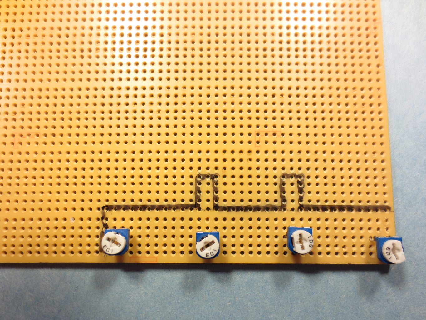
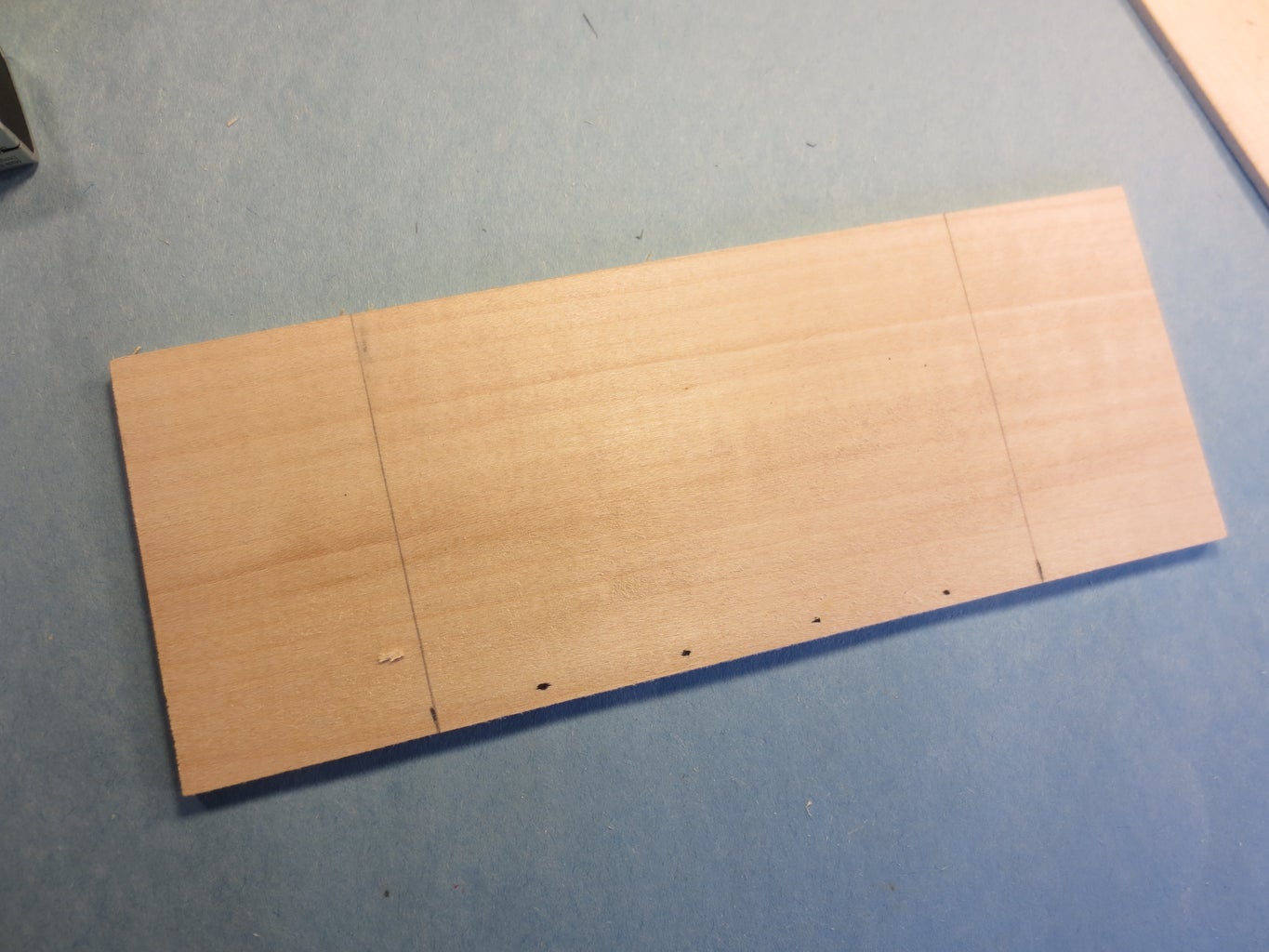
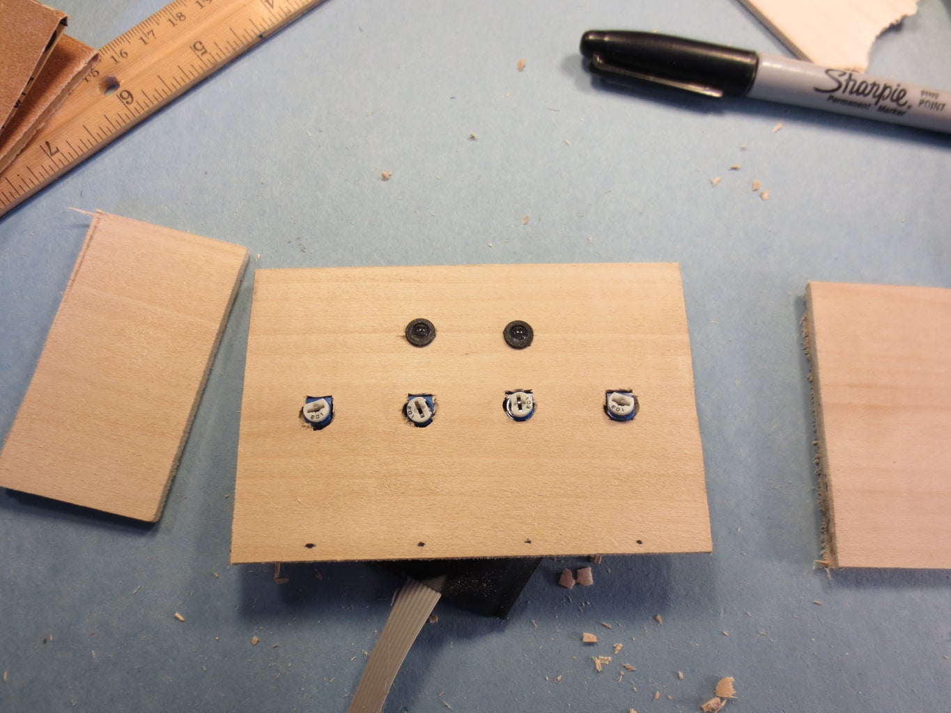
Anyways we're going to get started my drawing out a little template for the 2 LEDs (or one if you have RGB LED) and for the pots. I spaced the pots about 1 1/2 inches apart. Just keep in mind that you have to leave enough room for your turning knob. Cut out your template and solder all the components to it.
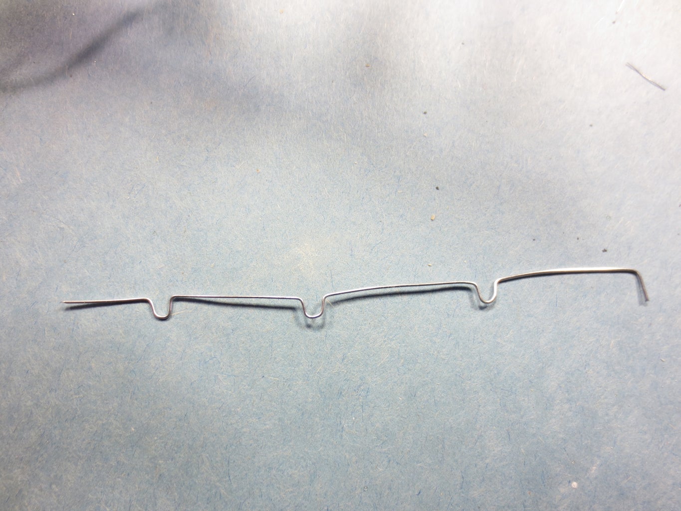
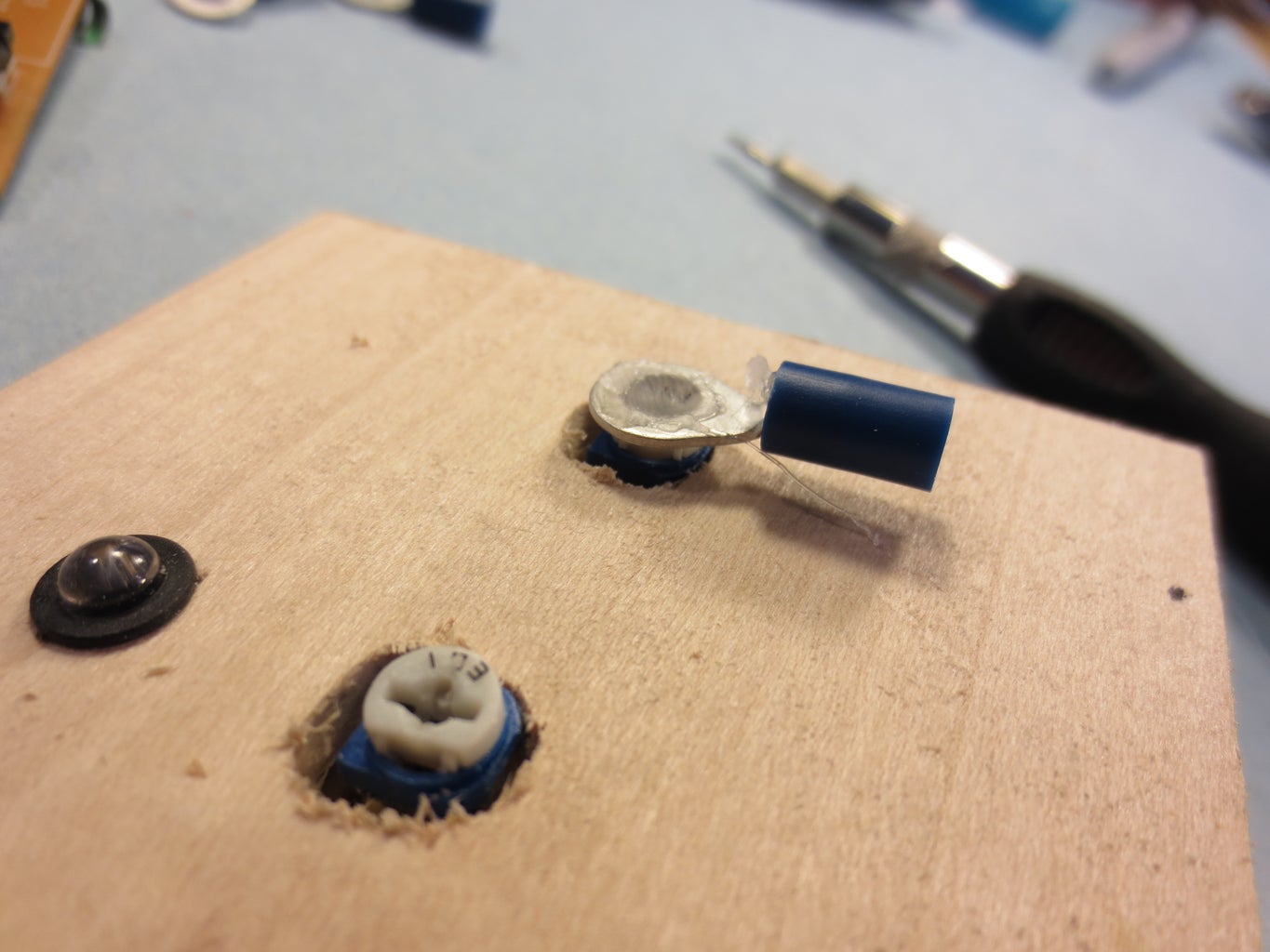
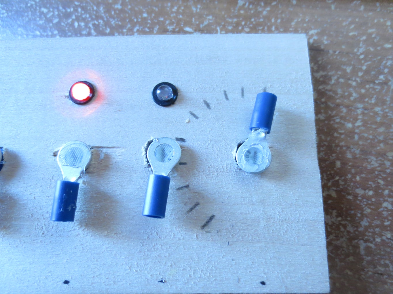
To connect all the potentiometers; begin by making a jumper like the one shown in picture 7. You don't have to do this, you could just use a insulated wire like I did with the positives. All the negatives (left side) connect together. Connect all the positives (right side).
Now, VERY IMPORTANT! TEST! You don't want to finish the project and then go, OH NO, it's not working!!!
To test, hook up the red wire (from the perf board) to 5v on Arduino and the black to GND. Connect your multimeter's black test lead to GND. Connect the red wire (of the multimeter) to the middle pin of the pots. Turning the pot should give you a read of 0 volts through 5 volts.
EVEN MORE IMPORTANT!
Make sure that when you solder the pots on they are all level and the same height. Otherwise, you will have horrible problems when it comes to adding the knobs.
Anyways we're going to get started my drawing out a little template for the 2 LEDs (or one if you have RGB LED) and for the pots. I spaced the pots about 1 1/2 inches apart. Just keep in mind that you have to leave enough room for your turning knob. Cut out your template and solder all the components to it.
To connect all the potentiometers; begin by making a jumper like the one shown in picture 7. You don't have to do this, you could just use a insulated wire like I did with the positives. All the negatives (left side) connect together. Connect all the positives (right side).
Now, VERY IMPORTANT! TEST! You don't want to finish the project and then go, OH NO, it's not working!!!
To test, hook up the red wire (from the perf board) to 5v on Arduino and the black to GND. Connect your multimeter's black test lead to GND. Connect the red wire (of the multimeter) to the middle pin of the pots. Turning the pot should give you a read of 0 volts through 5 volts.
EVEN MORE IMPORTANT!
Make sure that when you solder the pots on they are all level and the same height. Otherwise, you will have horrible problems when it comes to adding the knobs.
Step 3: Ribbon Cable Dissection & Soldering


Ribbon cable! My good friend gave me this from I guess his old computer. Whatever the FD drive is! So, using razor blade, separate 8 wires from the rest. Then I used some wire cutters to cut it. Strip the ends of the wires.
Soldering:
Working with ribbon cables can be tricky, but I found a way to master it. Draw a diagram! You can see in my diagram (the top) where everything should go. The bottom is just everything reversed because when I was soldering I was soldering with it upside down.
Soldering:
Working with ribbon cables can be tricky, but I found a way to master it. Draw a diagram! You can see in my diagram (the top) where everything should go. The bottom is just everything reversed because when I was soldering I was soldering with it upside down.
Step 4: Arduino Backpack


This is what others call a "shield", but I like 'backpack'. Now what's the purpose of this? It's so that if you need to use your Arduino for something else, you can just pull it off the top of the Arduino. If you want it back on, you can just push it right back onto Arduino!
Now there is a small problem with the pictures. I didn't put the open button on the inside of the door until later, so you won't see it in these pictures. Instead of making a 4 segment pin header make a 5 segment header.The fifth one will go in pin A4.
Now there is a small problem with the pictures. I didn't put the open button on the inside of the door until later, so you won't see it in these pictures. Instead of making a 4 segment pin header make a 5 segment header.The fifth one will go in pin A4.
- Lay the perf board on top of the the Arduino. Then stick some pin headers through the perf and into the Arduino's output pins. This is to hold the perf board on the Arduino. Using a sharpie, outline the Arduino on the perf.
- Cut the perf
- Mark a rectangle in the middle. Use a dremel to cut it out. I was able to cut it about halfway, then knock it out with a screwdriver.
- Cut off the pin headers. (1, 2, 2, 5)
- Place all the pin headers into the Arduino pins. (the 4 goes into pins A0-A3, one of the 2 goes into 5v and GND, the other 2 connects to pins 12 and 13, one of the 1 goes in A4, and the other 1 goes into pin 9.)(see pictures)
- Put the piece of perf on top of the Arduino, letting the pins slip in the holes.
- Put a drop of solder on top of the pins to hold them in.
- Feed the ribbon cable though the rectangle.
- Make all the solder connections. Be careful! Don't forget the resistors, pins 12 & 13!
- Cut off the connector of the servo and strip the ends.
- Attach the battery pack's positive and negative to the positive and negative of the servo.
- Solder the GND of the battery and servo to GND on Arduino.
- Solder the control wire of the servo to pin 9.
- Flatten out the tabs of a momentary push button.
- Clip one of the leads of a 10k resistor off and solder it to the switch.
- Solder a wire to the other end of the resistor.
- Solder a wire on before the resistor on the same pin.
- Solder a red wire on the other pin of the push button.
- Cover all the connections with heat shrink.
Step 5: Testing:
Now testing is always a good thing. It always good to know whether your project is working or not! Upload this code and open up serial monitor. See the video. Serial monitor is on the right. Warning: This is not the final sketch! This is just to test the pots!
Step 6: Making the Front Panel


So I just took a piece of basswood and marked off where all the potentiometers where. Then I took a ruler and drew the same marks in the middle. Using a 3/8 drill bit, I cut drilled the holes for the pots. MAKE SURE then pots fit in and are nice and level! For the LEDs just use a 1/4 drill bit as usual.
When you are putting on the ring terminals, MAKE SURE THAT THE POT IS TURNED ALL THE WAY TO THE LEFT FIRST!
Calibrating-
To do this you need to load the sketch to your Arduino and open up serial monitor. Slowly turn the knob. In serial monitor when it says 1, make your first mark. When it says two, make your second mark etc..
Making a frame-
Using some basswood sticks, I cut them to length and glued them on the edges. See photos.
I attached some double-sided tape to the battery holder, Arduino and the wooden frame.
After yo put the LEDs in sand them down the the height of the holder for some diffusion.
Step 7: Making the Servo Holder


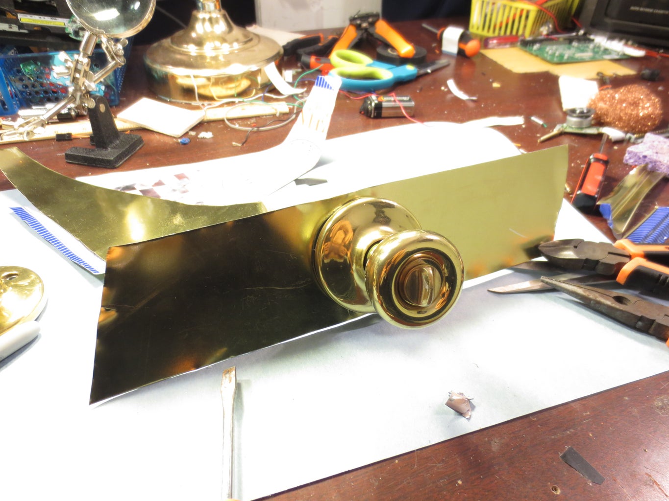


So I'm sure you can use some type of aluminum sheet metal, some type of laser cut acrylic, or 3D printed holder, but I don't have any of those. So I used a metal lid to a game. I was able to use my old pair of scissors to cut it up. BE CAREFUL, THE EDGES ARE SHARP! What I did is kinda hard to explain so just go through the photos one by one.
Step 8: Final Pictures


Step 9: Breaking Down the Arduino Code

Now the whole point is to learn, right? Now what do we want to happen? See the flowchart above. Let's get started by adding all of the pins.
This is just setting up all the pins. I'm not going to waste any time explaining this.
Setting up the the outputs.
buttonState = digitalRead(button1);
This is setting the words 'buttonState' the the digital reading at pin button1, which is pin A4. Since it's using the digitalRead function 'buttonSate' can either be HIGH or LOW.
int analog1 = analogRead(A0);
This is for taking an analog reading at pins A0. The analog reading is 0-1023.
int pot1 = analog1 * (10.0 / 1023.0);
Convert the analog reading from pin A0 to 0-10 from 0-1023
The rest of the code is for the other analog readings on the others pins A0-A3.
This is to test the following: If pot1 is equal to 4, and if pot2 is equal to 5, and if pot3 is equal to 6, and if pot4 is equal to 1, do the following. Change the numbers pot1,2,3,and 4 equal to create your own code.
Let's add another if statement
elseif (buttonState == HIGH) Is the digital reading at pin A4 high??? Yes, it is! So do. . .
else
{
digitalWrite(greenLED, LOW);
digitalWrite(redLED, HIGH);
myservo.write(170);
}
Now you may have noticed I added a delay in the button block, but not the pot block. Well the reason why I did this is so that you don't have to hold the button. If you look over the code, you will see that there are no delays, so Arduino is constantly doing the loop over and over and over again at a very fast speed. So the code says, "if the button is high, unlock the door'. Well if you release the button, the loop is looped and it sees the the button is not HIGH, so it locks the door. With the delay, once it detects the button is pushed, it will preform our action (unlocking the door, changing the LEDS), then is wait for 5 seconds before running the loop again. If you don't understand, try it. Take out the delay and see what happens.
This is just setting up all the pins. I'm not going to waste any time explaining this.
Setting up the the outputs.
buttonState = digitalRead(button1);
This is setting the words 'buttonState' the the digital reading at pin button1, which is pin A4. Since it's using the digitalRead function 'buttonSate' can either be HIGH or LOW.
int analog1 = analogRead(A0);
This is for taking an analog reading at pins A0. The analog reading is 0-1023.
int pot1 = analog1 * (10.0 / 1023.0);
Convert the analog reading from pin A0 to 0-10 from 0-1023
The rest of the code is for the other analog readings on the others pins A0-A3.
if (pot1 == 4 && pot2 == 5 &&
    pot3 == 3 && pot4 == 6)
Now this is where you need to put you your own combination in. I'm going to make mine 4536. This is to test the following: If pot1 is equal to 4, and if pot2 is equal to 5, and if pot3 is equal to 6, and if pot4 is equal to 1, do the following. Change the numbers pot1,2,3,and 4 equal to create your own code.
 {
   digitalWrite(greenLED, HIGH);
   digitalWrite(redLED, LOW);
   myservo.write(90);
 }
Let's add another if statement
elseif (buttonState == HIGH) Is the digital reading at pin A4 high??? Yes, it is! So do. . .
 {
   digitalWrite(greenLED, HIGH);
   digitalWrite(redLED, LOW);
   myservo.write(90);
   delay(5000);
 }
If either of these if statements aren't true, then do the following:else
{
digitalWrite(greenLED, LOW);
digitalWrite(redLED, HIGH);
myservo.write(170);
}
Now you may have noticed I added a delay in the button block, but not the pot block. Well the reason why I did this is so that you don't have to hold the button. If you look over the code, you will see that there are no delays, so Arduino is constantly doing the loop over and over and over again at a very fast speed. So the code says, "if the button is high, unlock the door'. Well if you release the button, the loop is looped and it sees the the button is not HIGH, so it locks the door. With the delay, once it detects the button is pushed, it will preform our action (unlocking the door, changing the LEDS), then is wait for 5 seconds before running the loop again. If you don't understand, try it. Take out the delay and see what happens.
Step 10: Final Arduino Sketch
If you can tell the code is 4561. Notice that I change these numbers up a bit from the previous code. Note: You will most likely have to change the servo values. Start off with 90˚ and slowly work your way up and down. You don't want to break your servo! For powering the Arduino I used a USB cable and a USB cell phone charger so I could have my lock constantly running!
Step 11: Conclusion:
I hope you guys enjoyed this i'ble! If you like it, vote it as a winner for the UP contest and the Make-to-learn Contest!
Please post your pictures of yours and if you have any question leave them in the comment box below or PM me.
P.S.
I didn't think about adding the pushbutton until after I had finished the project, so I'm sorry that some of the pictures don't align with the text.
Cheers!
Please post your pictures of yours and if you have any question leave them in the comment box below or PM me.
P.S.
I didn't think about adding the pushbutton until after I had finished the project, so I'm sorry that some of the pictures don't align with the text.
Cheers!
