

Introduction: Arduino Intervalometer


Hello and welcome, today I'm making an intervalometer for my Canon camera.
The sketch gives you control over the Number of frames The time between frames The total time required and the Shutter speed, when you have put your camera into bulb mode.
It will also display how long the time-lapse movie will be once compiled.
Step 1: Parts List

I'll be using the following parts
- An ARDUINO
- A Nokia 5110 Screen
- 5 Buttons
- 1 NPN Transistor (BC547)
- 2 x 10K Resistors
- 1 x 2.5mm Jack
- Some Wire
- A slice of Vero board and
- A battery pack
Step 2: The Code
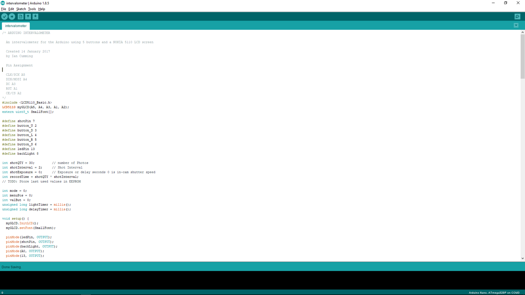
I'm using the LCD5110 Basic Library from http://www.rinkydinkelectronics.com/
<p>#include <lcd5110_basic.h><br>LCD5110 myGLCD(A5, A4, A3, A1, A2);
extern uint8_t SmallFont[];</lcd5110_basic.h></p>
I've used defines for each of the pins Initialized the variables used
<p>#define shotPin 7<br>#define button_U 2
#define button_D 3
#define button_L 4
#define button_R 5
#define button_S 6
#define ledPin 13
#define backLight 8
int shotQTY = 30;         // number of Photos
int shotInterval = 2;     // Shot Interval
int shotExposure = 0;     // Exposure or delay seconds 0 is in-cam shutter speed
int recordTime = shotQTY * shotInterval;
// TODO: Store last used values in EEPROM
int mode = 0;
int menuPos = 0;
int valBut = 0;
unsigned long lightTimer = millis();
unsigned long delayTimer = millis();</p>
Set up each pin and initialized the display in the Setup function
<p>void setup() {<br>  myGLCD.InitLCD();
  myGLCD.setFont(SmallFont);</p><p>  pinMode(ledPin, OUTPUT);
  pinMode(shotPin, OUTPUT);
  pinMode(backLight, OUTPUT);
  pinMode(A0, OUTPUT);
  pinMode(13, OUTPUT);</p><p>  pinMode(button_U, INPUT_PULLUP);
  pinMode(button_D, INPUT_PULLUP);
  pinMode(button_L, INPUT_PULLUP);
  pinMode(button_R, INPUT_PULLUP);
  pinMode(button_S, INPUT_PULLUP);
  digitalWrite(ledPin, LOW);
  digitalWrite(backLight, LOW);</p><p>  lightTimer = millis();
}</p>
In the main Loop I have a switch routine that decides what should be done.
- Case 0 updates the display
- Case 1 handles what happens when the buttons are pressed and
- Case 2 handles the taking of photos with the values calculated from case 1
<p>void loop() {</p><p>  switch (mode) {
    case 0: //Screen update
      myGLCD.clrScr();
      myGLCD.print(">", 0, (menuPos * 8));
      myGLCD.print("Frames", 8, 0);
      myGLCD.print("Pause", 8, 8);
      myGLCD.print("Time", 8, 16);
      myGLCD.print("Bulb", 8, 24);
      myGLCD.print("Start", 8, 32);
      myGLCD.print("(Play " + String(shotQTY / 30) + "\"" + String(shotQTY % 30) + ")", CENTER, 40);
      myGLCD.print(String(shotQTY), RIGHT, 0);
      myGLCD.print(formatTime(shotInterval), RIGHT, 8);
      myGLCD.print(formatTime(recordTime), RIGHT, 16);
      myGLCD.print(bulb(shotExposure), RIGHT, 24);
      mode = 1;
      break;
    case 1: // Check button States and do calculations for variables</p><p>      // Control back-light timeout
      if (millis() - lightTimer > 10000) {
        digitalWrite(backLight, HIGH);
      } else {
        digitalWrite(backLight, LOW);
      }</p><p>      // Buttons pressed?
      if (!digitalRead(button_D)) {     // Down Button
        while (!digitalRead(button_D)); // De-bounce
        menuPos = (menuPos + 1) % 5;
        mode = 0;
        lightTimer = millis();
      }
      if (!digitalRead(button_U)) {     // Up Button
        while (!digitalRead(button_U)); // De-bounce
        menuPos = (menuPos + 4) % 5;
        mode = 0;
        lightTimer = millis();
      }
      valBut = 0;
      if (!digitalRead(button_R)) {     // Right Button
        while (!digitalRead(button_R)); // Deb-ounce
        valBut = 1;
        mode = 0;
        lightTimer = millis();
      }
      if (!digitalRead(button_L)) {     // Left Button
        while (!digitalRead(button_L)); // De-bounce
        valBut = -1;
        mode = 0;
        lightTimer = millis();
      }
      if (!digitalRead(button_S)) {     // Enter Button
        if (menuPos == 4) {
          valBut = 1;
        } else {
          valBut = 2;
          digitalWrite(shotPin, HIGH);
          digitalWrite(ledPin, HIGH);
          while (!digitalRead(button_S)); // De-bounce
          digitalWrite(shotPin, LOW);
          digitalWrite(ledPin, LOW);
          lightTimer = millis();
        }
        mode = 0;
      }</p><p>      // Calculate values not changed
      if (abs(valBut) == 1 ) {
        switch (menuPos) {
          case 0:
            shotQTY += valBut;
            shotQTY = max(shotQTY, 1);
            shotInterval = max(recordTime / shotQTY, (shotExposure + 1));
            shotInterval = max(shotInterval, 1);
            recordTime = shotQTY * shotInterval;
            break;
          case 1:
            shotInterval += valBut;
            shotInterval = max(shotInterval, (shotExposure + 1));
            shotInterval = max(shotInterval, 1);
            recordTime = shotQTY * shotInterval;
            break;
          case 2:
            recordTime += (valBut * 30);
            recordTime = max(recordTime, 1);
            shotInterval = recordTime / shotQTY;
            shotInterval = max(shotInterval, (shotExposure + 1));
            shotInterval = max(shotInterval, 1);
            break;
          case 3:
            shotExposure += valBut;
            shotExposure = max(shotExposure, 0);
            if (shotInterval <= shotExposure) {
              shotInterval = shotExposure + 1;
            }
            recordTime = shotQTY * shotInterval;
            break;
          case 4:
            mode = 2;
            break;
        }
      }
      break;
    case 2:</p><p>      digitalWrite(backLight, HIGH);
      digitalWrite(ledPin, LOW);
      while (!digitalRead(button_S)); // De-bounce
      myGLCD.clrScr();
      myGLCD.print("START", CENTER, 8);</p><p>      delay(1000);</p><p>      int so;
      unsigned long countDown = millis();</p><p>      if (shotExposure == 0) {
        so = 100;
      } else {
        so = shotExposure * 1000;
      }
      delayTimer = 0;</p><p>      for (int t = -1; t < shotQTY;) {</p><p>        if (!digitalRead(button_S)) {
          t = shotQTY;
        }</p><p>        if ((millis() - delayTimer) >= (so)) {
          digitalWrite(ledPin, LOW);
          digitalWrite(shotPin, LOW);
        }</p><p>        if ((millis() - delayTimer) >= (shotInterval * 1000)) {
          t++;
          delayTimer = millis();
          digitalWrite(ledPin, HIGH);
          digitalWrite(shotPin, HIGH);
        }</p><p>        if ((millis() - countDown) % 1000 >= 990) {
          myGLCD.clrScr();
          myGLCD.print("REMAINING", CENTER, 8);
          myGLCD.print(String(shotQTY - t), CENTER, 16);
          myGLCD.print(formatTime(recordTime - ((millis() - countDown) / 1000)), CENTER, 24);
        }</p><p>      }</p><p>      digitalWrite(ledPin, LOW);
      digitalWrite(shotPin, LOW);</p><p>      digitalWrite(backLight, LOW);
      myGLCD.clrScr();
      myGLCD.print("DONE", CENTER, 8);
      delay(1000);
      while (!digitalRead(button_S)); // De-bounce
      lightTimer = millis();
      mode = 0;
      break;
  }</p><p>}</p>
I've created a function to display the time in minutes and seconds instead of only seconds.
<p>// Make the time Readable<br>String formatTime(int x) {
  String m, s;
  m = "";
  if (x / 60 >= 1) {
    m = String(x / 60) + "'";
  }
  s = String(x % 60) + "\"";
  return m + s;
}</p>
A function to show the word CAM when bulb mode is not selected.
<p>// Make the time Readable<br>String bulb (int x) {
  String h = String(x) + "\"";
  if (x == 0) {
    h = "CAM";
  }
  return h;
}</p>
Attachments

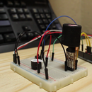
Step 3: The Circuit
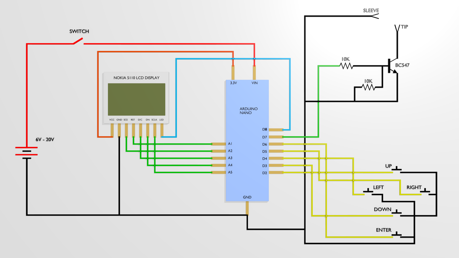

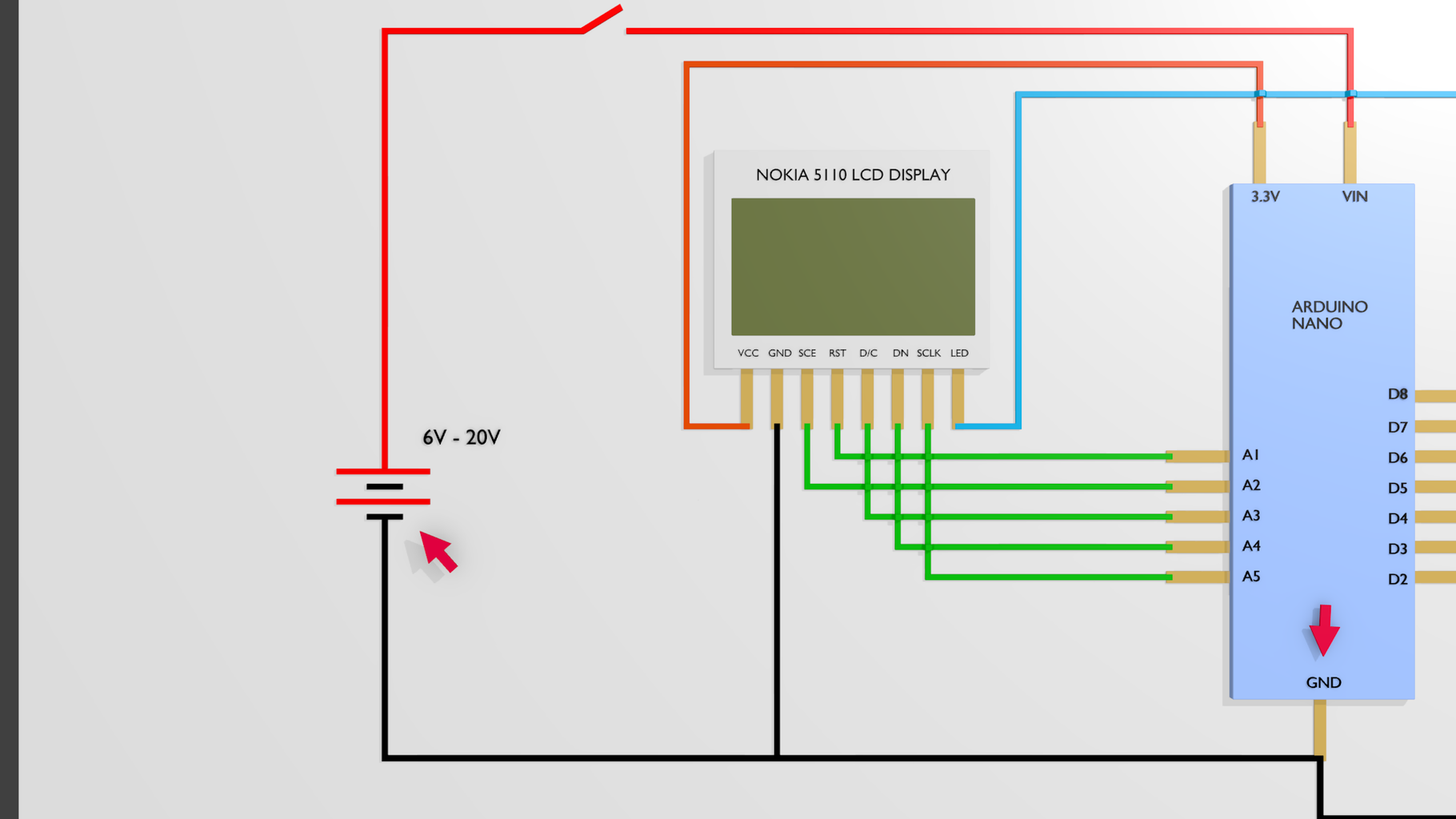


Battery:
- Connect a 6v to 20v battery to the Vin pin of the Arduino and
- Connect the negative to the Ground of the Arduino
I've tested it with a 5v Battery pack and it still works but the screen does not always operate as it should.
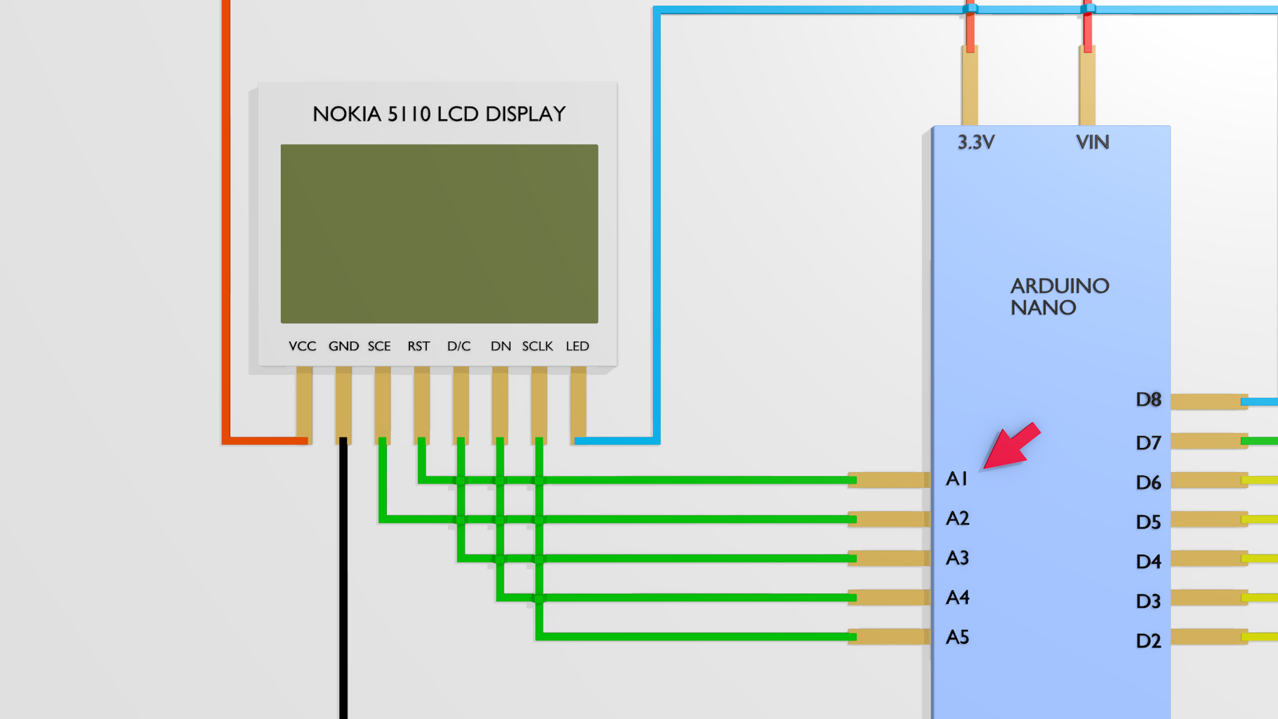
LCD Screen:
Connect the Screen up to A1 through to A6,
- RST goes to A1
- CE/CS goes to A2
- DC goes to A3
- DIN/MOSI goes to A4
- CLK/SCK goes to A5
2.5mm Jack:
- The tip of the Jack goes to the Collector of the Transistor
- The Sleeve of the Jack goes to the Emitter of the Transistor and to the Ground of the ARDUINO
- A 10K resistor goes between the Emitter and the Base of the transistor
- And the other 10K resistor goes between the Base and pin 87 of the Arduino
Buttons:
All the buttons are connected to ground
The other side of the buttons hook up to pins 2 through 6 of the Arduino
- Up goes to D2
- Down goes to D3
- Left goes to D4
- Right goes to D5 Enter goes to D6
Attachments
Step 4: Conclusion
It took some time to get all the parts soldered together.
The circuit works as predicted, put it into an enclosure, preferably something a little more professional looking than my cardboard box, and your intervalometer is all set to go!

Participated in the
Arduino Contest 2017

Participated in the
Remote Control Contest 2017


