

Introduction: Arduino LED Cube With Android Remote

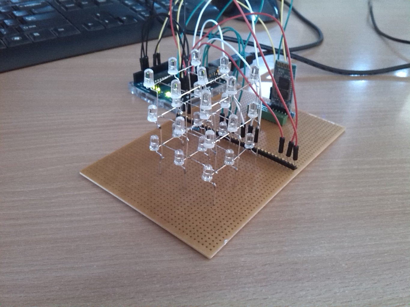


A 3x3x3 LED Cube connected to an Arduino Uno that can be controlled using an Android phone with RemotyXY via Bluetooth connection. This was a school project and also my very first project using Arduino. Because of this I will try to keep this tutorial as simple as possible with simple examples so they might help other beginners.
In this tutorial I will show you how to create the following:
- 3x3x3 LED Cube with Arduino
- Setup for Bluetooth Module and Arduino
- Connecting to the LED Cube using RemoteXY
How it works:
The cube consists of 3 layers, each has 9 LED's. The 3 layers have negative pins and the 9 LED's have positive pins. This way, using the Arduino to control the pins, each individual LED can be controlled.
Useful links:
- http://circuitdigest.com/microcontroller-projects/... this helped me build my cube
- https://create.arduino.cc/projecthub/user206876468... this helped me test my Bluetooth
- http://remotexy.com/en/ the app I used
Step 1: Requirements
Materials:
- Arduino Uno (Starter Pack)
- 27 LED's (I ordered 30 just in case)
- Conductor wires
- 3 Resistors (82Ω)
- Bluetooth Module HC-05
- Perf board (comes with Arduino Uno Starter Pack)
- 19 wires (also comes with the Starter Pack)
Tools:
- Soldering iron
- soldering
- 32 Female headers (16 would be enough but leaving spots open between wires makes soldering much easier)
- 6 Female connector
- Needle Nose Pliers (for bending the LED's)
- Pliers (for cutting the wire)
Misc:
- Button cell battery 3V (e.g. CR2032) (optional)
- Pencil
- Paper
- Ruler
- Tape
- Foam or cardboard
- White acrylic paint (e.g. Tamiya XF-2)
Step 2: (Optional) LED Checkup
Just in case, check each LED with a button cell (I used CR2032). Finding out a LED is faulty after soldering everything together will be a pain to replace.
Hold the positive side of the LED (slightly longer side) to the side with the plus of the button cell and the negative side of the LED to the negative side of the button cell. This should light up the LED.
Step 3: LED Template

First we are going to create the template for the LED's. On a piece of paper, draw a square with 9 circles, like the picture above. These circles mark the position of the LED's. The circles should be about 2cm apart.
Place the piece of paper on top of your piece of foam or cardboard and put some sticky tape on all corners so it won't move from it's position.
Now put holes in each of the 9 circles on your template. Make sure the holes are about the size of a LED. They need to stick in the hole without falling out. I used a simple pencil to make the holes.
Step 4: Creating the Layers


First, we are going to create one layer (9 LED's).
Put the LED upside down and bend the positive side into an 'L' shape, like in the picture. Hold the LED with the positive side at 12 o'clock and bend the negative side 90 degrees to 3 o'clock.
This is done so the positive sides can touch the positive side of the LED beneath it and the negative side can touch the negative side of the LED right next to it.
Place this LED into your template and repeat this for every LED in the layer. When all 9 LED's are placed. Solder the negative sides together. Try to keep the solder not too long near the LED as the temperature might burn the LED down. The 3 negative sides that are on the outside can be cut in half using a plier.
Now place 2 conducting wires between the rows and solder them together so they're all connected, see the figure.
If you use transparent LED's paint the bottom side of the LED's to prevent false light in the upper layers. I painted the bottom with white acrylic paint.
Repeat this for the remaining 2 layers.
Step 5: Combining the Layers
Take 2 layers (from the previous step) and place both on their side with the positive sides (the 'L' shapes) and place them so both layers touch with about 5mm. Now solder them together.
Do the same for the final layer and you should have a 3x3x3 cube.
Place the cube inside your perf board. Keep about 2 cm between the board and the LED's, of course you can place it as low as you want but I personally did 2cm because the rest of my LED's also have 2cm between them. The remainder can be cut off using a plier.
Using conductor wire, connect each layer to the perf board, by connecting one of each layer's negative pins that's sticking out (the ones we cut in half in the previous step) to the board. Try to keep some space between them to make the soldering a bit easier. We will connect everything in the next part.
Step 6: Wiring the Cube


Solder everything thats sticking out underneath the board to the female headers. Make sure you cut off any long parts first. The negative wires (i.e: the layers) require resistors to be connected between the headers and the cube.
Make sure you keep things grouped. Keep rows close together to keep them grouped and organized. I kept each row close together. 1, 2 and 3 are one row with red wiring, 4, 5 and 6 have white wiring and 7, 8 and 9 are green. The negative wires (the layers) have black wiring.
Now connect the Arduino to the headers. Use same colored wires for same groups to keep things organized and easy to adjust.
Place the negative wires from your cube into A0, A1, and A2 on your Arduino, with the upper layer in A0 and the bottom layer in A2.
Place the positive wires into digital 4 up to 12. Number 1 on the figure goes to pin 4 with number 9 into pin 12
Step 7: Testing the Cube
Now that we have everything in place let's test if it works! Download "LEDCubeTest.ino" below and upload it to your Arduino. It wil enable and disable every LED one after another. If it doesn't go in order one of your wires may not be connected to the right port.
Attachments

Step 8: Adding Bluetooth


Now that we have a working LED Cube let's add Bluetooth.
Add your female connectors (minimum size of 6) to your board and place your female headers (minimum size of 7) near it. Now solder each female connector to the nearest header.
The wiring:
- RXD goes to digital port 3
- TXD goes to digital port 2
- GND goes to GND
- VCC goes to 5V
Don't worry about any resistors, the Bluetooth Module can handle the Arduino's 5 Volt.
Step 9: Connecting to Android
To connect the Bluetooth Module to your Android phone you can of course write your own app, but if you're in a hurry or simply don't feel like writing your own, you can use RemoteXY. This is a very simple framework that does most of the work for you.
First download the RemoteXY library. Everything is explained here: http://remotexy.com/en/help/how-install-library/
Once everything is installed go here: http://remotexy.com/en/editor/ to create an interface for your app. For now just drag a 'switch' element onto the screen make sure the switch's variable name is "switch_1". Once done, click on "get source code".Here you can see the generated code, for now download "RemoteXYTest.ino" below to get the code for our LED Cube.
Download RemoteXY from the Appstore. Once downloaded, tap the 'plus' icon, then select Bluetoothand connect to your Bluetooth Module. The password of your Bluetooth module will be either '1234' or '0000'. The app should have the interface you just created. Press the switch to see the lights go on or off.
Now you can go and create your own interface and light variations. Don't forget that the free version of RemoteXY only allows up to 5 interface elements.
To use the interface I created click here and download "LEDCubeFinal.ino" below for the source code with 7 different settings.


