

Introduction: Arduino Lockbox With Solenoid and RFID & Custom Hardware
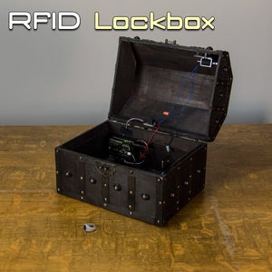


Let's make a lockbox! We went over the main points of this project in the Arduino Controlled Lock Box with Solenoid and RFID, but a lot of people were left feeling like we didn't spend an adequate amount of time with customization options and the general hardware build. In this instructable, we're going to cover the ins and outs of setting up the hardware necessary to make a simple RFID enabled solenoid powered lock box!
Step 1: Project Parts List
- Any box with a hinged lid. We used one we found on Amazon.
- 1 x Geekduino
- 1 x RFIDuino Shield
- 1 x Relay
- 1 x Solenoid (a small solenoid will work for most cases)
- 1 x Power Squid
- 1 x 90 Degree DC Jack
- 1 x 6V2A Power Supply (or higher if you have a larger solenoid. Check your solenoid specs before selecting a power supply.)
- 2 x Wire Nuts / Solder
- Screws, nuts, bolts, hardware (as needed)
- Some Delrin or other thin, strong material.
If you are new to RFID, we recommend sticking with the RFIDuino Shield as your RFID reader so that the sample code provided runs without a hitch, and you can refer to our documentation if you run into any issues.
In this instructable, we're going to get a little more hands on with the hardware than we have in the others, so let's make sure we have some tools before we get started.
Tools:
- A Dremel with wood/plastic/metal engraving bits
- A Drill with an M3 drillbit
- a jigsaw with blade that can cleanly cut wood/plastic
Step 2: Let's Make a Latch Plate!


Here we have provided a template for making your own latch plate. The design considers that you may need to adjust the plate vertically to get a proper latch, because this will be mounted on the inside of a box, and measurements can be challenging. This will give you the leeway you need to guess and check without damaging your box or having to re-drill holes to make adjustments.
Get a piece of delrin or other material that you have access to the tools to modify (a drill, dremel tool, and jigsaw). Wood is acceptable, but the more solid the material, the less likely you are to have breakage. You shouldn't get a piece of material more than 4mm thick. The throw on a small solenoid is just under 5mm, so this will allow the solenoid a fair amount of room to do its work.
You could also laser cut or 3D print the latch plate if you'd rather save the effort for the fun stuff. We have a laser cutter that we make our delrin parts on, but we did it by hand just to prove that it can be done.
To make the latch plate by hand:
Print out the latch plate template, cut it out, and mark your material. If you are using a larger solenoid, you will have to modify the top hole to allow the plunger to pass through. The bottom slots are made to accommodate M3 bolts. If you are using a different size bolt, make sure to modify the bottom slots to allow your bolt to pass through, but also so that the latch plate can be held in place with nuts.
Now that your material is marked, drill holes at each end of the slots with a drill or dremel tool. You can drill multiple holes in series for the small slots and clean up by pushing from one hole to the next in line with the dremel. If your slots look rough, a file can smooth out the barbs.
Once your holes are drilled, cut the straight lines and rounded outer corners with the jigsaw. You can finish the edge with some sandpaper or a file for a clean look and paint it to match, or just leave it raw, as it will not affect the functionality of the latch. Ours isn't pretty. We're sorry. It totally works though, we swear. We checked it!
Now put the latch aside, we have one more plate to make.
Step 3: Make the Solenoid Adjustment Plate


In order to clear the latch plate, we will need to be able to adjust the position of the solenoid to match. This can be done through careful measuring, but since the tolerances of the materials leave very little room to work with, it's best that we be able to adjust the position of the solenoid easily. Let's make a solenoid adjustment plate!
As with the latch plate, you could also laser cut or 3D print the solenoid adjustment plate if you'd rather save the effort for the fun stuff. We have a laser cutter that we make our delrin parts on, but we did it by hand just to prove that it can be done.
To make the Solenoid Adjustment Plate by hand:
This plate was designed to be used with the RobotGeek Small Solenoid. If you are using another solenoid, you will have to design your own adjustment plate, keeping in mind the idea is to allow you to slide the entire solenoid parallel to the plunger.
Print out the solenoid adjustment plate template we've provided here. Cut it out, and mark your material. Drill holes at each end of the slots with a drill or dremel tool. You can drill multiple holes in series for the small slots and clean up by pushing from one hole to the next in line with the dremel. If your slots look rough, a file can smooth out the barbs.
Once your holes are drilled, cut the straight lines and rounded outer corners with the jigsaw. You can finish the edge with some sandpaper or a file for a clean look and paint it to match, or just leave it raw, as it will not affect the functionality of the adjustment plate. This one doesn't look too pretty either, but just like with the last one, it totally works!
Step 4: Drill Some Holes in Your Box, and Start Mounting!


Using the templates we cut out, drill your mounting holes near the middle of the slots, giving you the most room for adjustment. The idea is to attach the Latch plate to the side of the box, and the solenoid plate on the top of the box in such a way that the tip of the plunger will intersect with the latch plate when trying to close it.
Using some double stick foam, you can mount the antenna at the front of the box, and the relay anywhere out of the way.
You can use double stick foam to attach the arduino to the box, but it is advisable to mount it with bolts to save on mess if you would like to one day retrieve it for another project.
Drill a hole that fits your DC Jack in the back of the box somewhere inconspicuous, close enough to where you mounted the arduino, leaving enough room to plug everything in.
Step 5: Get Your RFID Tag ID

In order to use our RFID tag, we're going to need to know its ID to program into the board. Connect your RFIDuino into the computer as shown above.
You're going to need the RobotGeek Tools and Libraries ZIP file for a sketch that will allow you to read your card data to the serial monitor. The RobotGeek Tools and Libraries Download offers a variety of sketches and libraries for working with RobotGeek Robot Kits. The libraries folder contains libraries that will add functionality to your Arduino, while the RobotGeek Sketches folder contains behavioral code for robots, as well as tools for testing. Install it by adding these two folders to your Arduino user folder.
Open the RFIDuino_helloworld sketch. This can be found under:
File>Examples>RFIDuino>RFIDuino_helloworld
You will need to make sure the code is adjusted for your RFIduino hardware.
v1.2 shields (2 pin antenna, 'REV 1.2' printed on the board) will need the following code
RFIDuino myRFIDuino(1.2); //initialize an RFIDuino object for hardware version 1.2
v1.1 shields (4-pin antenna, no version number printed on the board) will need the following code
RFIDuino myRFIDuino(1.1); //initialize an RFIDuino object for hardware version 1.1
Both lines of code are available in the RFIDuino_helloworld sketch, simply uncomment the one you don't need. If you are still unsure about what hardware you are using, see this page
Connect a micro USB cable from your computer to your Geekduino
Load RFIDuino_helloworld onto your board using the upload button in the Arduino IDE.
Once loaded, you can leave your board connected to your computer - you will need this connection to power the board and to communicate with the computer
Open the Serial Monitor.
The serial monitor should be set to its default settings ('No Line ending', 9600 baud)
Swipe a tag across the RFIDuino antenna. The green light will light up and your buzzer will make a noise.
The Serial Monitor will display 5 numbers separated by commas. These numbers make up the ID of your tag.
Copy down these numbers for future use. It can be handy to write the ID on a sticky note and attach it to the tag.
Tags in the EM4102 protocol have 64 bits that they return to the RFID reader. 24 of these bits are used for communication / protocol information (9 header bits, 10 parity bits and a stop bit.) This leaves 40 bits, or 5 byte for the tag's ID. The RFIDuino library returns the tag's ID as an array that contains these 5 bytes. All of the RobotGeek tutorials will use this convention for dealing with the Tag's ID number, displaying the tag id as 5 numbers in decimal format. However here are many ways that you can represent this number.
Step 6: Wiring and Programming

Follow the diagram to wire your parts.
- Open
RFIDuino_demo2_lockboxonto your board. You can find this sketch underFile>Examples>RFIDuino>RFIDuino_demo2_lockbox
- You will need to make sure the code is adjusted for your RFIduino hardware.
v1.2 shields (2 pin antenna, 'REV 1.2' printed on the board) will need the following codeRFIDuino myRFIDuino(1.2); //initialize an RFIDuino object for hardware version 1.2
v1.1 shields (4-pin antenna, no version number printed on the board) will need the following codeRFIDuino myRFIDuino(1.1); //initialize an RFIDuino object for hardware version 1.1
Both lines of code are available in the
RFIDuino_demo2_lockboxsketch, simply uncomment the one you don't need. If you are still unsure about what hardware you are using, see this page - You will also need to modify the sketch to include the ID of a tag that we found in Hello World . Find line 57 - it looks like this.
byte key_tag[5] ={0,0,0,0,0};Now insert the ID numbers for your tag. For example, if our tags ID was '70 0 44 22 242' we would modify the code to look like thisbyte key_tag[5] ={77,0,44,22,242}; - Connect a micro USB cable from your computer to your Geekduino
- Load
RFIDuino_demo2_lockboxonto your board using the upload button int the Arduino IDE. - Once loaded, you disconnect the USB cable from your computer..
- Swipe the 'key' tag across the RFIDuino antenna. The green light will light up and your buzzer play three different notes. Additionally, the solenoid will fire.
- Swipe any tag that is not the 'key' tag across the RFIDuino antenna. The red light will light up and your buzzer play three monotone notes. The solenoid will not react.
Step 7: That Was Fun!
So what are you going to do with your custom built RFID lock box? Have anything you want to store? Maybe you could re-enact the briefcase scene from the end of pulp fiction with some lights inside the box? What about adding a servo or linear actuator to lift the lid? Maybe you could make a music box by having the buzzer play a little tune while the lid is open? There is so much fun you can have with this, and we'd love to see what you come up with!


