

Introduction: Arduino RC Amphibious Rover


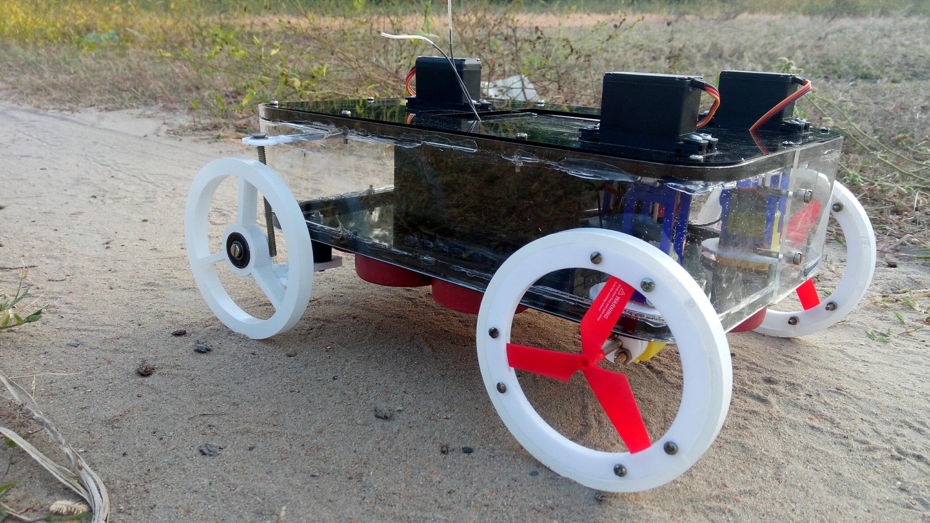


Over the last couple of months we have been developing a remote controlled rover that can move both on land and on water. Although a vehicle with similar features uses different mechanisms for propulsion we tried to achieve all the means of propulsion by using wheels alone.
The vehicle consists of a floating platform with a pair of wheels that are integrated with a propeller. At the heart of the system is the versatile Arduino UNO which control the motors and various mechanisms.
Follow on to see the transformation between the terrestrial and the aquatic form of the Amphibious Rover!
If you liked the project do vote for us in the contests (on top right corner)
Step 1: Using Fusion 360 to Develop the Concept

We started by making a sketch of this project and we soon realized the complexity of building an amphibious rover. The key issue is that we are dealing with water and mechanisms that actuate, two aspects that are difficult to combine.
Therefore within a week using Autodesk's free 3D modelling software called Fusion 360 we developed our first designs to reinvent the wheel! The whole process of modelling was easy to learn with some help from Instructables' very own 3D Design Class. The following steps highlight key features of our project and give a better understanding of the inner workings of the rover.
Step 2: Developing the Wheels


After a lot of brainstorming we came to the conclusion that it would be cool if we managed to use the rover's drive system to work both on land and on water. By this we mean instead of two different ways to move the rover our goal was to integrate both into one mechanism.
This led us to a series of prototypes of wheels which had flaps that could open up, giving it the ability to move water more efficiently and propel itself forward. The mechanisms on this wheel were far too complex and had several flaws, this gave inspiration to a much simpler model.
Eureka!! We got the idea of fusing a propeller into the wheel. This meant that on land, it would roll smoothly, while in water, the spinning propeller would push it forward.
Step 3: Creating a Pivoting Axis


With this idea in mind, we needed a way to have two modes :
- In the first one, the wheels would be parallel (like a normal car) and the rover will roll on land.
- For the second mode, the rear wheels will have to pivot in a way that they are at the back. This will allow the propellers to be submerged under water and push the boat forward.
To execute the plan of pivoting the rear wheels, we thought of mounting servo motors to the motors (which are connected to the wheels) to rotate them back.
As seen in the first picture (which was our initial model) we realized that the arc created by the revolving of the wheels, interfered with the body and therefore needed to be removed. However this would mean that a large section of the slit would be open to water getting in. Which obviously would be disastrous!!
The next picture shows our final model, which solves the previous issue by lifting the body above the pivoting plane. That said a section of the motor is submerged, but since this motor has a plastic gear box, water isn't an issue.
Step 4: Pivoting Unit


This unit is the mechanism behind the rotation of the back wheel. The DC motor needed to be attached to the servo motor so we built a "Bridge" which fits onto the motor and into the servo horn.
As the motor has a rectangular profile when rotated it covers an area having the shape of a circle. Because we are dealing with water we can't have mechanisms which expose huge gaps. To fix this problem we planned to attach a circular disc to seal the hole at all times.
Step 5: Front Steering Mechanism

The rover uses two steering mechanisms. In water the back two servo motors are used to control the position of the propeller resulting in turning left or right. Whereas on land the front steering mechanism is used controlled by a front servo motor.
Attached to the motor is a link which when pushed towards the wheel makes it pivot around the "Golden shaft" in the picture. The range of pivot angle is around 35 degrees sufficient to make quick sharp turns.
Step 6: Transformation Mouvement


This is where a normal rover turns into an amphibious one, behold the transformation.
Step 7: Materials Needed:


Here is a list of all the components needed to make your very own amphibious rover. All the parts are easily available an a hobby shop.
ELECTRONICS :
- Arduino Uno - the brain of the rover, this powerful micro-controller will control the various motors on board.
- Motor Driver Shield - by mounting onto the Arduino Uno the L293D shield
- DC Motors with Gearbox x 2- the motors that will help in propelling the rover forward. The yellow gearbox is perfect as it can be submerged under water giving the project a lot more versatility.
- Futaba Servo Motor x 2- low cost and high performance motors. will act as the pivoting axis for the back wheels
- HiTech Servo Motor - very high torque motor will be used to steer the rover.
- 6 Channel Transmitter and Receiver - this versatile transmitter will control our rover wirelessly.
- 9v Battery x 2 - a lipo power bank would also do, we didn't have one so we used a pair of 9 volts. Down side it is not rechargeable.
MATERIALS & HARDWARE :
- Acrylic of thicknesses : 2mm, 3mm, 5mm, 10mm. Colors : Black, White, Translucent Blue, Clear.
- 1/4 Plywood
- Bearing x 2 - Specifications of 8mm bore and 22 mm outer dia.
- Propeller x 2 - three bladed ones which we salvaged from an old toy quadcopter.
- Rubber Rim
TOOLS :
- Hot glue
- CA glue
- Two part Epoxy
- Soldering Iron
- Drill
- Saw
- Laser-cutter
Considering that you have none of these parts an estimation for this project would be around 80 USD.
Step 8: Parts and Specifications


The complete list of all the parts to laser-cut with the name, color and thickness of the piece. Do have a look with the pictures it might help to better visualize.
Top Layer Black 3mm x 1
Bottom Layer Black 3mm x 1
- Side Frame Black 5mm x 2
- Side Wall Clear 2mm x 1
- Bridge Side Piece Blue 3mm x 4
- Bridge Top Piece Blue 3mm x 2
- Motor DisK White 3mm x 2
- Front Wheel White 10mm x 2
- Inner Rim (back wheel) White 3mm x 4
- Outer Rim (back wheel) White 10mm x 2
- Steering Link White 3mm x 1
- Compartment Box Black 3mm x 1
- Compartment Lid Black 3mm x 1 ( this section will be cut out from the "Top Layer" )
- Rear Motor Shaft White 3mm x 2
- Front Plat White 5mm x 2
Attachments

Step 9: Laser-Cut Parts


Using a graphic design software (Inkscape, link to this free software below) we drafted the parts we would need to make the amphibious rover, from the 3D model.
Then we took the design to a nearby workshop to get the parts laser cut. After laser cutting be sure to have 27 individual pieces. Now for a tedious and time consuming job start peeling off the protective plastic layer. This probably is also the most satisfying part!
All the files and information about the parts can be found in the previous step.
Step 10: Fitting the Servo Motors


To start of we attached the servo motors to the Top Layer.
You will need all three servo motors. The 2 Futaba ones will be attached to the back mounting spots and the HiTech on the front slot. Push in the rubber spacers into each hole of the servo motors, this will help in absorbing any kind of shock while moving. Then put each servo motor in it's respective spot facing downward, and screw them in tight from the top.
Step 11: Gluing the Nuts


The Top and Bottom layers can be unscrewed to access the inner mechanisms. To do so we made two frame pieces which will be attached to the transparent Side Wall with epoxy.
Start by taking 20 x M3 screws, and screw them on to the Top and Bottom layers with its corresponding frame. Then apply a small drop of CA glue to the nuts to hold them in place. Once the glue dries remove the bolts and strengthen the bond with epoxy. We mixed the two parts thoroughly and let it cure overnight. This fixes the nuts to the frame, and allows you to simply screw on the bolts.
Step 12: The Floats for the Bottom Layer


We hot glued floats to the Bottom Layer to keep the rover afloat. This will also prevent the water leveling rising and finally flooding the rover.
Simply position the floats in a somewhat "hydrodynamic" manner making sure they don't overlap or cover any holes. With a good amount of glue lock them in place.
Step 13: Making the Acrylic Bending Jig


Bending acrylic can be quite a tricky task as it needs to be heated while simultaneously shaping it to the desired contour.
The rover has a clear acrylic side wall so that one can see the inner mechanisms. To curve the sheet along the corners we require a proper jig that has the same profile of the Side Frame. Draw out the profile of the corners on a piece of wood to make your guide. Once done we cut the shape out using a jigsaw and lightly sanded it until it matched the template. We repeated the process 4 times making a solid block to get the right height.
Get a big sheet of wood and glue the block into place. Your guide is complete and you can now bend the acrylic sheet that will have even support.
Step 14: Heat and Bend


Clamp the acrylic to a straight end of the jig and then start heating the corner region making an up and down motion with a heat gun. After around 20 seconds the acrylic starts to become softer. At this point gently shape it around the curve with the help of a piece of scrap wood. Clamp it in that position and let it cool down. Repeat the same process for all 4 corners.
Tip : We would recommend that you test this process on a few strips of waste acrylic to get a hang of it.
Step 15: Adding the Side Frames


The Side Wall should now almost have the same profile as the frames. Leave a 3mm gap on both ends and glue the frames using epoxy. We used clamps to secure it in place. The 3mm gap is left to accommodate for the Top and Bottom Layers so that they line up flush when screwed in. Let the epoxy cure overnight.
Step 16: Rectifying the Issue


We ran into a small problem when we realized that the circular disc which needed to fit snugly onto one section of the motor had to cross several protrusions bigger than the rectangular cutout. With a couple of tools you will need to make several modifications so that the disc is able to get to the right spot.
Gather a blade, a saw and a pair of pliers.
Step 17: Modifying the Motors


Start by cutting off the plastic band which holds the motor in place with a blade. Then bend the plastic tabs (hook shaped) inwards with the help of pliers till it snaps. If you are finding it difficult you can simply saw it off flush. Believe it or not even the sticker was a bit too thick so we peeled it out. Once done you can effortlessly slip the disc in place. Keep following the pictures to remove any doubts.
Step 18: Attaching the Circular Discs


Now that there aren't any protrusions to interfere with the rectangular opening push the circular disc around the motor till it is just below the screw holes. Once in place we made sure that the disc was perpendicular to the motor body and then glued it in place. This will not only secure the disc but it will also seal the system and make it waterproof.
As the plastic band which held the motor needed to be cut, with a bead of hot glue around the motor fit it back in its slot. Do make sure that the teeth of the gear are matching by checking if the shaft rotates freely.
Step 19: Gluing the Motor Bridge Piece


Gather the pair of pieces that make the bridge that encapsulates the motor and connects to the pivoting rear servo motors. Interlock the finger joints and use CA glue to lock them in place, make sure to keep them perpendicular to one another. Repeat this for the other pair.
Step 20: Screwing on the Servo Horn


Get your cross-shaped Futaba servo horn, and using the mounting screws attach the horn. With the Bridge piece standing upright we positioned the horn facing up and used the inner most holes to fix the screws.
Step 21: Integrating the Propellers to the Back Wheels


This is the key step of the whole build, to finally integrate the propeller into the Back wheels. The props used for this project were salvaged from an old quadcopter (the links to get your own are mentioned in the ''Materials Needed'' step).
We took the pair of Inner Rims and screwed on 6 x M3 screws with nuts on the other end. Make sure not to tighten them fully as shown in the pictures.
Step 22: Clamping the Propeller


Then tug the two discs apart and slip in the propeller, making sure each blade goes between two screws. Try to center the propeller's shaft with the center of the Inner Rim with the help of a quick template. Once centered tighten the nuts squeezing the blades and securing them in place.
Step 23: Painting the Wheels White (extra Step)


Unfortunately the shop we went to laser-cut the parts didn't have 10mm acrylic in opaque white, instead we got the Front Wheels and the Outer Rim of the Back Wheels in 10mm clear acrylic. This wasn't a big issue but it didn't suit the overall appearance of the rover.
Therefore we gave it a light sanding and sprayed on a couple of coats of white spray paint. We let it dry for around an hour and made sure to apply even coats. Take your time while sanding as it will definitely help to grip the paint better.
Step 24: Fixing the Outer Rim


Now that the paint has fully dried, gently push in the Inner Rim with the propellers into the Outer Rim. The fit should be snug and should easily get in with the least force. However if for any reason, maybe due to the extra coat of paint, it feels too tight just lightly sand the inner rim. Don't try forcing it in as you risk breaking the thin Outer Rim. Now make sure to align the Inner Rim flush with one side of the Outer Rim as shown in the picture.
Step 25: Hot Gluing the Inner Rim


Once the two rims are completely flush, from the back of the wheel secure the Inner Rim with hot glue. Make sure to avoid sticking the nuts and concentrate on getting an even amount of glue all over.
As the Inner Rim is divided into two parts to hold the propeller, the outer part of the Inner Rim can still be taken out in case of any requirements to adjust the propeller or even if needed to change it. By gluing just the back half of the Inner Rim you offer an easy way to replace things in the future.
Step 26: Pushing in the Bearing


To complete the front wheels we need to simply push in the bearings. Fidgets spinners are rather useless but we broke open ours to salvage the bearings. We gently hammered in a nut which was nearly the perfect size as the diameter of the bearing's inner hole. This allows us to use a screw as an axle.
By giving an even pressure on all sides push the bearing in. Again if you feel its too tight lightly sand the inner hole of the Front Wheel. A block of wood can also help in maintaining an even pressure.
Step 27: The Completed Wheels

Spin your wheels making sure it turns smoothly and you are complete. Let's start inserting them into the rover's body!
Step 28: Making the Electronic Case


Get the pieces that form the compartment for the electronic components. Align the finger joints and use Ca glue to secure them together. Follow the animation to get the orientation right.
Step 29: Waterproofing and Sealing


The box that holds all the electronics components is one of the most important aspects and needs to be properly waterproofed for safety and also because it contains valuable parts. Once the CA glue has dried the box should be already rigid and firm.
Having finger joints give a strong bond but it doesn't seal the joints completely. One can use proper silicon sealant but from our experience hot glue works as well. We carefully applied a good quantity of hot glue on all the edges making sure to seal all the gaps.
Step 30: Making Wooden Supports for the Top Panel


The electronics compartment which is situated in the middle of the rover's body needed to be accessed from the Top Layer for convenience. Therefore we laser-cut a small square out of the Top Layer which acts as the lid to the compartment, making it easy to access and integrating it seamlessly into the design.
We made few supports that we mounted flush with the upper layer of the electronics compartment. This support will act as a material to also screw on the top lid. We found an old piece of plywood a 1/4 inch thick. Measure and mark out four squares with dimensions of 1.5 cm by 1.5 cm. An important note is that the lid is slightly smaller than the compartment's dimensions as increasing the lid would interfere with the servo mounting holes.
Cut out the four pieces of wood and make the required holes which are aligned with the holes on the lid piece. Then glue the supports on the corners of the compartment with CA glue keeping it flush with the top. Once done you can test fit the alignment by fitting the screws.
Step 31: Back Wheel to Motor Connector


We needed a way to connect the motor’s shaft to our hybrid rear wheels, so we custom-made our own connectors with acrylic. The connector is divided into 3 parts. The first has the same profile of the motor’s shaft which is cut-out on a disk. The next disk screws into the motor's shaft. The third and second disk help to clamp a bolt which fits into the wheel. Finally all three are held together with 2 screws.
Follow the animated GIF to help in assembling.
Step 32: Front Wheel Axle Assembly


Mount the screw through the bearing and on the Vertical piece of the Support to make an axle. Then join the two pieces with CA glue ( as shown in the animation). Once done fit in the front pivoting shaft and screw it on with a nut below. This will allow your Front Wheels to revolve freely. Finally attach the steering link with an aluminium rod to the outer hole.
Step 33: Electronics


Start off by plugging the motor driver shield into the arduino and place it inside the electronics box. Slip the two rear dc motor wires through the holes in the box, and connect the left motor wires to the port 1 (labelled as M1) and the right ones to the port 2 (labelled as M2).
Now slip the two rear servo motor wires through their respective holes and connect them to the two ports dedicated to servo motors on the shield. The left servo gets plugged into the port labelled as servo 1 and the right servo get plugged into the port labelled servo 2.
Next, pass the front servo motor's wire through the hole in the electronics compartment and attach its signal wire (usually yellow or white) to pin A3 on the motor shield. Then connect the power wire (red) to one of the power pins on the shield and finally connect the ground wire from servo (black) to one of the ground pins (gnd) on the shield.
Finally we need to add the receiver to the circuit. Ground (gnd) from receiver goes to one of the grounds (gnd) on the shield and +5v from receiver goes to one of the +5v pins on the shield.
- transmitter's throttle (usually pin 3) connects to pin A0 on the shield.
- transmitter's steering (usually pin 1) connects to pin A1 on the shield.
- transmitter's switch (usually pin 5) connects to pin A2 on the shield.
Once everything was connected we hooked up the battery to the power port (labelled as M+ and gnd) on the shield.
Refer to the circuit images attached above for any doubts.
Step 34: Downloading and Installing Additional Libraries


In this project you will need just one additional library: adafruit's motor shield library.
First you need to download the library from here. Once that's done open the arduino IDE. On the IDE navigate to Sketch>>Include Library>>add .ZIP library. Select the zipped folder that you just downloaded and hit open.
The library should have successfully installed into your IDE.
Refer to the attached images for any doubts.
Step 35: Programming

Once you are done attaching all the electronic components and installing the extra libraries, you can connect the arduino to a computer and upload the code that is attached below.
Note: It is always a good idea to keep the batteries disconnected from the circuit to avoid accidents that may damage your computer. Also, MAKE SURE to unplug the power jumper on the motor shield or you risk drawing way too much current from the little USB port and eventually burning it!
Make sure to keep the transmitter off while uploading the program to your arduino. Once the program is fully uploaded you can connect the batteries and turn on the transmitter.
Do a basic check of the rover's actuators by gently pushing on the sticks on your transmitter.
Troubleshooting:
- if you see any of the actuators not behaving the correct way, check for a loose connection
- in case any of the two rear motors spin the wrong direction when you throttle forward, simply swap the motor pins going to the shield
- if the steering turns in the opposite direction, go to your transmitter's settings or menu and reverse the steering channel. This varies from model to model but should be explained in the transmitter's manual or on the internet.
Attachments
Step 36: Putting the Parts Together (Top Assembly)


This is the final process of assembling the rover, here are the steps :
- Run the program making the servo motors orient in the right position. (the neutral position)
- Fit in the two Bride Pieces so that the Vertical Pieces face the rover's side.
- From the bottom screw in the horns to secure them to the servo motors.
- Then attach the DC motors to the Bridge pieces.
- Fix the Top panel with the Top Support frame and Side Wall
- Slip the Steering link through the slot on the Side wall and screw it on the Hitech Servo motor's outermost hole. Add the center screw too.
- Fix the pivoting shafts and the Electronics Compartment to the Bottom panel to the Bottom Frame.
- Connect the Back Wheel to the motors.
- Connect the Front wheels.
- Wire up the electronics
Now bring your rover to life by switching on the switch on top!
Step 37: Assembly Continuation (Bottom Assembly)


The continuation of the bottom Assembly to make things...
7.Fix the pivoting shafts and the Electronics Compartment to the Bottom panel to the Bottom Frame.
8.Connect the Back Wheel to the motors.Connect the Front wheels.
9.Wire up the electronics.
Now bring your rover to life by switching on the switch on top!
Step 38: Understanding the Controls

The rover has two modes, the first, is the ability to roll like a normal car on the ground; the second mode allows it to transform into a boat that can move through water. The selection of the mode is done with the switch attached to channel 5 on your radio control. When the switch is off the rover is in the car-mode, but when you turn the switch on, it transforms itself into the boat-mode by turning its hybrid wheels to face back.
The controls are straightforward:
- the throttle is on the left stick on the radio control in the up and down axis
- the steering is on the right stick on the radio control in the left and right axis
Make sure the transform switch works (test this out by holding the rover up off the ground). When it is in the car-mode the steering is done with the front wheels. In the boat-mode the steering is done with the rear two servo motors by facing them in the opposite direction that the rover wants to turn.
Once you have tested all the functionalities, you are ready to put the rover to its real test.
Step 39: Testing Your Very Own Amphibious Rover


Power up the Rover, go out and have some fun!
This project was a whole lot of fun to make and we hope you enjoyed it too. Although it definitely needs further improvements and iterations this could be a concept that can have potential in the future. In today's world the process of making and developing has become very powerful with tools like CAD, Laser-cutting and 3d printing that all that the maker needs is innovation.
So reinvent things, like our wheel, to keep making small advancements in technology. Happy making.
We will be happy to offer any suggestions to those interested in replicating this project. Do drop a comment for feedback or questions in the comments section below.
Don't forget to vote if you liked this project .
Cheers!
