

Introduction: Arduino Top 10 Must Know Basics


Now that you’ve heard about the Arduino Microcontroller and maybe even run out and bought one, how do you do things with it? When you’re just getting started with tinkering, the questions can be non-stop. Obviously, a sense of patience and curiosity are staples, but everything else is something you can learn, so here are my Top 10 Basic Arduino Must Know Factoids to help you get tinkering!
Throughout this Instructable I tried to include some basic code to use with the components. It is not the complete list, just a good starting point. Watch the punctuation and caps, they matter (I think I caught any mistakes), you do not need to indent, I did that to draw attention to the code used in a routine or section.
When you’re ready to move on and want more, I recommend Arduino.cc and Adafruit.com as the best 2 places to start but look around, there are plenty of good sites available including, obviously, here on Instructables. On a side note, as you search for Arduino sites to use, you may notice that there is an Arduino.cc and an Arduino.org. You can research why, but the .CC is the site to use. My opinion and goto source.
Step 1: Serial Communication (Output for Now)

Not the dispenser for your breakfast, but output to help you see what is happening with your Arduino program. When the Arduino is connected via USB to the computer and running the Arduino IDE (Integrated Developer Environment - the application you use to code the Arduino), you can request information to be output to the screen. Use it whenever something may not be doing what you think it should, you can monitor, check, see output, see values, read input, or just about anything that might help point to a problem.
The Serial connection uses Digital pins 0 and 1 to communicate. If you plan on using it, don’t use these pins!
As you get more familiar with Arduino programming, you will also discover that you can input to the serial monitor and interact with the program. We’ll save that for another time.
To use the Serial Communication:
Include this line in your setup() routine:
Serial.begin(9600);
To output data to the screen, use this in any of your routines:
Serial.print( what you want to see ); or
Serial.println ( what you want to see ); The ln at the end places a carriage return after the line.
Step 2: LEDs

Light Emitting Diodes can be useful for any project. From feedback to games to just cool, LEDs can “brighten” any idea. They also are a great place to start learning and practice interacting with the Arduino.
When using LEDs with an Arduino output (5v), be sure to use a resistor, without a resistor, an LED will quickly burn out - and you will get to experience the magic smoke (yeah, it is a thing). You can use any one of several good online resistor calculators if you want to start getting more in depth.
All LEDs are not created equal. Different colors use/consume different voltages and amps. Typically, Blue and White are on the high end using around 3.2v and 25 mA. Yellow and Green use about 2.1v and 20mA and Red uses the least at about 2v and 15mA. Even different LEDs of the same color can use different amounts, but these are good estimates to use. In my experience though, a 200-220Ohm resistor on an LED provides enough Lumen without danger and gives me a constant to use.
To use an LED in your code:
first, declare the LED in your opening. This establishes ‘led’ as an integer on Pin 2.
int led=2; (you can use any name, not just led)
Use this format for 2 reasons - it makes it human recognizable (pin 2 is my LED) and if you change the pin assignment, it will change the call throughout the program. Notice I didn’t use O or 1 as those are for Serial communication.
in the setup() routine, declare it as an output:
pinMode(led, OUTPUT);
Now, whenever you want to turn the led on and off, in any routine:
digitalWrite(led, HIGH); or
digitalWrite(led, LOW);
Step 3: Buttons

Buttons are the easiest and likely most popular way to interact with the Arduino when starting out - or for any project. Buttons close a circuit and trigger an action when read by the Arduino. Using the digitalRead() command will determine if the value is HIGH or LOW, the result is then used to make something happen. When using buttons, be sure to use a resistor to ground - 10K is recommended - to avoid a false read.
To start using buttons and LEDs, set up the blink example included with the Arduino IDE.
To use a button, it is very similar to our LED configuration above.
Start by declaring the button in the opening
int button=3; establishes our button on pin 3.
in setup():
pinMode(button, INPUT);
In any routine, read the button as on or off using an integer to record the state
int buttonRead = digitalRead(button);
From here, use that information to do something
if(buttonRead==1){
doSomething;
}
This set reads the state of the button and if it is pushed (HIGH or 1), it will do something.
Step 4: Potentiometers

Also known as POTs, the potentiometer is just a variable resistor that can manipulate the voltage to a component. POTs have 3 legs (5v, data, Grd) and are controlled via a knob or turn screw. POTs are available in a spectrum of levels, measured by their maximum Ohms, with 10K being one of the most popular. When you turn the knob, the Ohms are either increased or decreased, from its minimum to its maximum. As an example, if you use a POT with an LED, the result is it will brighten and dim the LED as you rotate the knob. Another use for them is to read the level with the analogRead(), which will return a value from 0-1023, which can be used as a variable.
To use the POT as part of your code declare the POT in the opening:
int POT=A0; will be read on Analog pin 0
in the setup() routine:
pinMode(POT, INPUT);
and in any routine:
int readPOT = analogRead(POT);
There’s that value holder again. If you need this value in other routines, declare it in you opening so it will be a global variable and not just local. The reason to use the place holder is if you just tried to Serial.print(POT); after the read, you would get 0 (based on A0, which is what you assigned it). By using the readPOT variable, Serial.print(readPOT); will return the actual reading.
Step 5: Voltage Converters

While not necessarily one of the most used components for the Arduino, they are just a personal favorite for what you can do with them. When you use a voltage converter, you are really just using a POT (see #4) on a board that can increase or decrease the overall amount of current input. You adjust the output voltage up and down by using the attached POT, but the really useful part is that they can provide a stable level of voltage that is less (buck converter) or more (boost module) than what actual input voltage is used. As an example, they can be used when your input (from your power cord) is a single 5v input but you want to run a motor that requires 12v. The boost allows for a single power cord to make enough voltage for the different component. In Eighth grade science, Mrs. Hoyle said that matter can neither be created nor destroyed, she never said anything about energy, bwahaha.
Note: Use caution when using boost converters and acquire them from reputable sources as really cheap boosts can have consequences. Also, be sure to look at step #10 if you need to use a relay to activate a component.
Using a voltage converter does not require any special coding or recognition in your code.
Step 6: DHT11 (and 22 ) Temp and Humidity Sensor

These are great little devices for making simple weather stations and environment sensors. The DHT11 and DHT22 are inexpensive devices and easy to incorporate into a project. For more detail check out the adafruit.com website and don't forget to #include the dht.h library.
While not a steadfast rule, I have noticed that many DHT11 sensors are blue and DHT22 sensors are white. Not a fact for all units, but just a side note to help determine which you might have at a glance.
to use a DHT module in your project you need to include a library for reference.
In your opening include the following:
#include “DHT.h”
int myDHT = 2;
float humidity, temp, tempF;
#define DHTTYPE DHT11 (or DHT22 depending on which you use)
DHT dht(myDHT, DHTTYPE);
in the setup() routine:
dht.begin();
In any routine:
humidity= dht.readHumidity();
temp= dht.readTemerature();
To convert to Fahrenheit:
tempF= (temp*9/5)+32;
Step 7: Real Time Clock (RTC)

Starting with this group (steps 7-10), be prepared to do some research, googling, or exploration to get proficient. I want to introduce the hardware and some basic coding start points, not write an entire book (which some have done) on using these components in creative ways for projects. Refer to the Arduino and Adafruit sites, check out other Instructables or any of the thousands of related sites that will help you. Much of the setup code can be found in the examples included with the Arduino IDE, take advantage of them.
Back to our hardware. RTCs are used to keep time, perform tasks at specific times or intervals and whatever else your imagination can conjure. One of the more commonly used RTCs is the 3231 but you may see 1307, etc.. Each is a little different and the focus here is on the 3231 (arguably the better version). You need to use a library (recommend RTCLib - get it here) to access the functions which include seconds, minutes, hours, day, date, month and year. The RTC uses a 2032 3.2v battery so you can disconnect power and not lose settings, when purchasing a unit, try to find ones using the 2032R (rechargeable) batteries.
When wiring the RTC you need 4 wires - 5v, Grd, SDA (pin A5) and SCL (pin A4).
These are marked on the pins at the base of the RTC.
You will need to have the RTCLib library installed in your Arduino IDE library. Since we are dealing with hardware today, if this is not there or you have questions, please go Here (Adafruit site).
Since using the RTC and time and calls is more than this intro can provide, please use the link above for more detail or open the ds3231.ino example from the RTCLib folder on the Arduino IDE.
That said, here are some basic code snipets to get started.
in your opening include:
#include<wire.h>
#include “RTClib.h”
RTC_DS3231 rtc;
int hour=now.hour();
int minute=now.minute();
in your setup() include:
rtc.begin();
wire.begin();
DateTime now=rtc.now();
in any routine, as examples:
Serial.print(hour);
Serial.print(minute);
if(hour>8){
doSomething;
}
Before you can use the RTC the first time, you must run a setup “program” to set the time. Again, see the link above for more detail or see one of the several Instructables (like this one from LsHallo).
Step 8: LCD Displays

Liquid Crystal Displays are an easy way to get your project up and running with feedback - or maybe just snappy responses. The LCD Display comes in 2 main varieties: 2 lines with 16 characters (2x16) or 4 lines with 20 characters (4x20). Both work and are wired the same way, just different sizes. The LCD display is a great place to start when you are beginning because they are fairly inexpensive, easy to write to and, as you gain experience, can do some basic animations and custom characters.
When planning your projects, the LCD, like most displays you will use, consume valuable Digital Pins on your Arduino. The LCD uses 6 of them, so plan accordingly. You only get 13 digital I/O pins on the Uno and if you use D0 and D1 for your Serial Communication (see #1 above) that leaves potentially only 5 usable pins! If you do find a project that needs more I/O (input/output) pins consider moving up to an Arduino Mega with 54 digital pins or making use of the Analog pins - some of which can be used for digital I/O as well.
To use an LCD Display: in your opening include:
#include <LiquidCrystal.h>
LiquidCrystal lcd(12,11,5,4,3,2);
These are the pins you’ve used to connect the display if you followed the graphic
In the setup() routine:
lcd.begin(16,2) or (20,4) for the larger LCD
In any routine you can use:
lcd.setCursor(0,0);
lcd.print(“ your text here “);
The command setCursor() starts your text at column 0 (first character box) on the top row - line 0. (0,1) would be column 0, second line, up to (15,1) for the last column, second line - or just (the column, the line).
Use double quotes to place text, no quotes if you are printing output from the Arduino, for example:
lcd.print(tempF); from the DHT11 in step 6 would display the Temp in Fahrenheit.
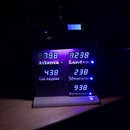
Step 9: TFT Displays

The TFT (Thin Film Transistor) display is when you get ready for some more serious graphics. TFTs come in a variety of sizes, display various fonts, use color and are able to display .BMP pictures to liven up your project as long as your TFT has the SD reader on the back. If you really want to impress you can even get touch screen versions for input. Coding for the TFT is a bit more work, but in the end, worth the trouble. Again, when planning your project, be wary of the number of pins consumed. A basic TFT uses 5 pins, with .BMP pictures 6 pins, and for touch 8 pins.
To use your TFT, you may need to add some libraries from Adafruit - I know, i reference them a lot, but they do so much for the Arduino and Raspberry Pi tinkers out there (shameless plug for them, support them when you can by buying their products! You won’t be disappointed in them or the services they provide).
My example assumes you wire the TFT: CS pin 9, RST 7, DC 8, SCLK 13, DIN (MOSI)11.
In your opening include:
#include<Adafruit_GFX.h>
#include<Adafruit_ST7735.h>
#include<SPI.h>
#define CS 9
#define RST 7
#define DC 8
Adafruit_ST7735 tft=Adafruit_ST7735(CS, DC, RST);
in your setup(), clear and refresh the screen:
tft.initR(INITR_BLACKTAB);
tft.fillScreen(ST7735_BLACK);
Colors that seem to be predefined: BLACK, RED, GREEN, YELLOW, WHITE but you can find codes for thousands of colors to be included.
in any routine you can use:
tft.setCursor(0,0); to start text or output, (X,Y) location in pixels
tft.setTextColor(ST7735_YELLOW); to set the text color
tft.setTextSize(1); 1 is smallest, 4 is the largest
tft.print(“ your text here “); use the same rules as the LCD
There is a lot more you can do to draw and print to the screen, Adafruit has a great documentation guide that will tell you all you need to know (.PDF document).
Step 10: Relays (and Motors)

While motors are a fun way to do things with the Arduino, let’s focus on the relay for now. This will allow you to use motors or any other higher voltage draw components with your project (including AC items).
Note: Use CAUTION when using relays, while simple devices, they can be dangerous if used or wired incorrectly. Start with low voltages, get comfortable, then move up. You have been warned and this is just an introduction instructable!
Relays are really just a switch for turning devices on and off, just like a light switch. When activated by the Arduino, they allow current to pass separate from the Arduino to the device to activate. When using relays, you will need a current that is separate from the Arduino. While you can use the same power source, you need to draw the power directly from the source by using a terminal block or splitter for the current.
To use the relay with a motor, again, provide a separate power feed for the motor.
Now let’s use a button on pin 2 to activate the relay on pin 3.
in the opening:
int motorButton = 2;
int motorRelay = 3;
in the setup() routine:
pinMode(motorButton, INPUT);
pinMode(motorRelay, OUTPUT);
digitalWrite(motorRelay, HIGH);
This last line is optional and only for NO wiring (see the graphic) and prevents the motor from starting on startup.
in any routine, just check the button - see step 3. To activate put this in the ‘if’ statement:
digitalWrite(motorRelay, LOW); Turn the motor ON by activating the relay
delay(2000); Run the motor for 2 seconds
digitalWrite(motorRelay, HIGH); Turn the motor OFF by deactivating the relay
Step 11: Final Words...
So there they are my top 10 Arduino Basics to get started. I hope you find them useful and will have an opportunity to try them all in your projects!
For ideas on what you can do with your Arduino be sure to check out some of my other Instructables as well as the thousands of great ideas throughout this amazingly informative site!
I have a follow up series for more advanced techniques and components in the works, so give me a like and stay tuned if this was helpful.
Good luck, be safe, and Happy Tinkering!


