

Introduction: Arduino Ultrasonic Alarm


Using an Arduino UNO, an Ultrasonic Sensor, and a RFID Reader, you can create a simple alarm which when placed near a door, senses if that door has been opened or if someone has come in and triggers an alarm which would sound a buzzer and flash a set of LEDs until its shut off.
With an Ultrasonic Sensor, the alarm goes off when the individual or object passes the sensor at less than a certain distance set in the Arduino (ie. 36 inches), thus creating a restricted perimeter near the door rather that detects an object going in. Once the alarm has been triggered, it remain on until either the alarm is deactivated, power is cut to the Arduino, or a certain amount of time passes (ex. 10 minutes), whichever comes first.
Activation of the alarm is controlled using an RFID Reader which renders the alarm on and off when the appropriate tag/card is flashed in front of the reader. If an unauthorized tag/card is detected, the reader will reject it, and the alarm's state will not change. The tag/card can be used to activate and deactivate the alarm when entering or leaving, as well as deactivate the alarm when triggered.
For this project, the following sources were used as references and guides for setting up and programming the Arduino:
- http://www.hw2sw.com/2012/09/07/connecting-a-magne...
- http://makezine.com/projects/pir-sensor-arduino-al...
- https://www.instructables.com/id/SIMPLE-ARDUINO-ULT...
- http://www.makeuseof.com/tag/how-to-make-a-simple-...
- http://www.makeuseof.com/tag/how-to-make-a-simple-...
- https://www.instructables.com/id/How-to-use-a-Buzz...
- http://www.makeuseof.com/tag/how-to-make-a-simple-...
- https://create.arduino.cc/projecthub/Aritro/secur...
Step 1: Required Supplies / Programs


You will need:
- 1 Arduino UNO (or Genuino UNO) - https://www.arduino.cc/en/Main/arduinoBoardUno
- 1 Type A/B USB 2.0 Cable (Should already be included with your Arduino UNO)
- 1 Breadboard - https://learn.adafruit.com/breadboards-for-beginn...
- 1 Mifare MFRC522 RFID Reader/Writer - http://playground.arduino.cc/Learning/MFRC522
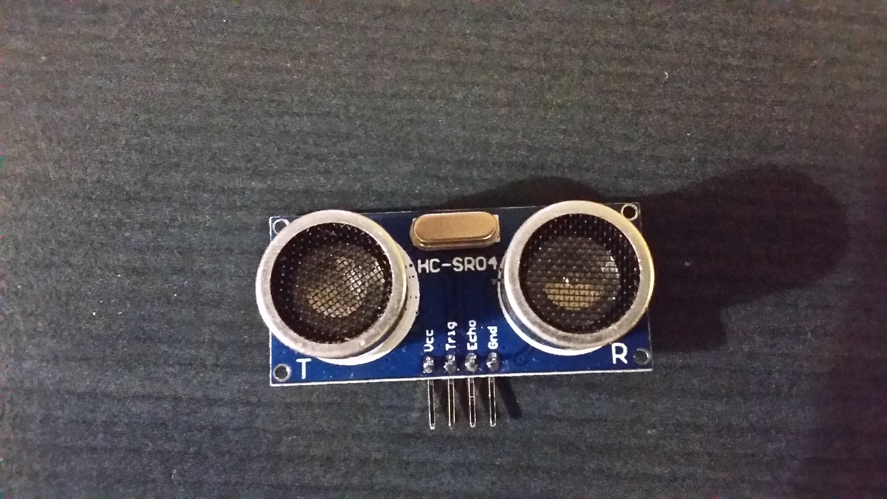
- 1 HC-SR04 Ultrasonic Sensor - https://www.sparkfun.com/products/13959
- 1 Piezo Buzzer - https://www.adafruit.com/product/160
- 2 or more LEDs (preferably those of different colors to provide better visual indication) and 270 Ω Resistors (red, purple, brown stripes) - https://learn.adafruit.com/adafruit-arduino-lesso...
- Jumper Wires - https://www.adafruit.com/product/758
In terms of software, you will also need:
- Latest version of the Arduino Software (IDE) - https://www.arduino.cc/en/Main/Software
- MFRC522 Library - https://github.com/miguelbalboa/rfid
Step 2: Install the Arduino Software IDE and All Necessary Libraries


First, install the Arduino Software from their website: https://www.arduino.cc/en/Main/Software
You can their use the installer to directly install it to your machine or (if you are using Windows) download the ZIP archive and extract the ready-to-use application without the need to install anything.
Now, the application already comes with the library for the Ultrasonic Sensor but if it doesn't or its not up to date, you need to manually add it:
- Open up the Arduino application. A new window with a blank sketch should pop up (this is where your code will go).
- Click on 'Sketch' in the toolbar, go to 'Include Libraries', and then click on 'Manage Libraries...'
- In the Library Manager, type 'hc-sr04' in the search bar, find and select the "Ultrasonic" Library, and then click on 'Install' to add the latest version.
For the RFID Reader/Writer, you will need to manually add this library, as it doesn't come packed with the software:
- Download the RFID ZIP file from GitHub: https://github.com/miguelbalboa/rfid
Now, if your using the Arduino ZIP Archive, you should be able to extract and copy the library directly to your Arduino's 'libraries' folder. For more information, go to https://www.arduino.cc/en/Guide/Libraries. But if you have an installed version of Arduino:
- Open up the Arduino application.
- Click on 'Sketch in the toolbar and select 'Add .ZIP Library'.
- Locate and select the ZIP Library you downloaded from GitHub and select 'Open' to add it.
Your Arduino IDE should be ready for code to be added and now is the time to set up the Arduino UNO itself.
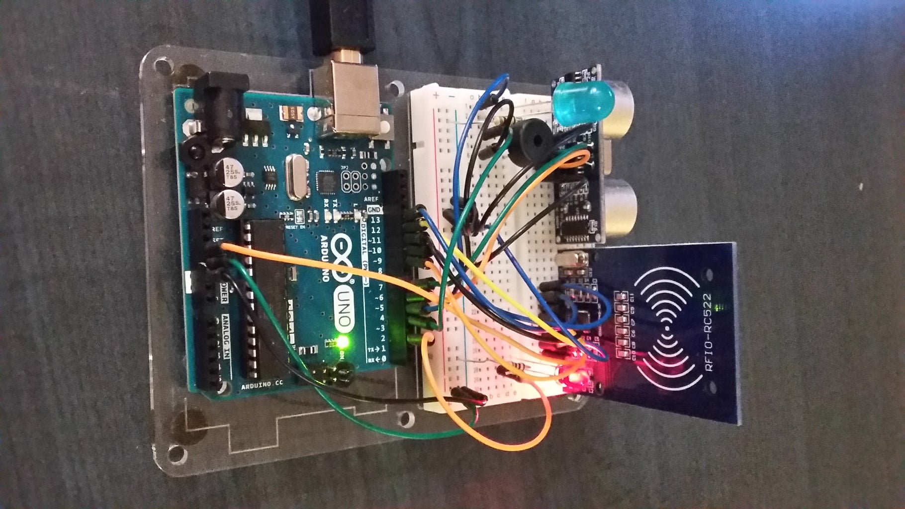
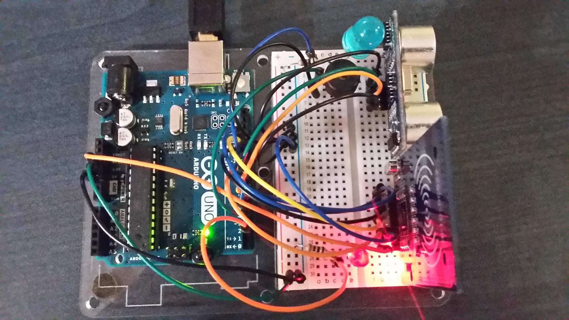
Step 3: Wire Up the MFRC522 RFID Reader/Writer


Next, you will need to wire up the RFID Reader, as there are some things you will need to do with this before setting up the rest of the alarm:
- Connect two wires from the positive and negative points of the power rail (ie. the rows on either side of the breadboard) on the breadboard to the 5V and GND Pins on the UNO (this will act as your main power source for the later components).
- Plug the RFID Reader into the breadboard. Ensure that the reader is mounted vertically, otherwise power will not flow properly to it.
- Connect wires from each of the following points on the RFID Reader to these Digital Pins on the UNO:
- SDA => Digital Pin 10
- SCK => Digital Pin 13
- MOSI => Digital Pin 11
- MISO => Digital Pin 12
- GND => GND (you can connect this either directly to a GND Pin or to a negative point on the power rail)
- IRQ => ***NOT USED***
- RST => Digital Pin 9
- 3.3V => 3.3V Pin (DO NOT CONNECT IT TO 5V AS THIS WILL DAMAGE THE READER)
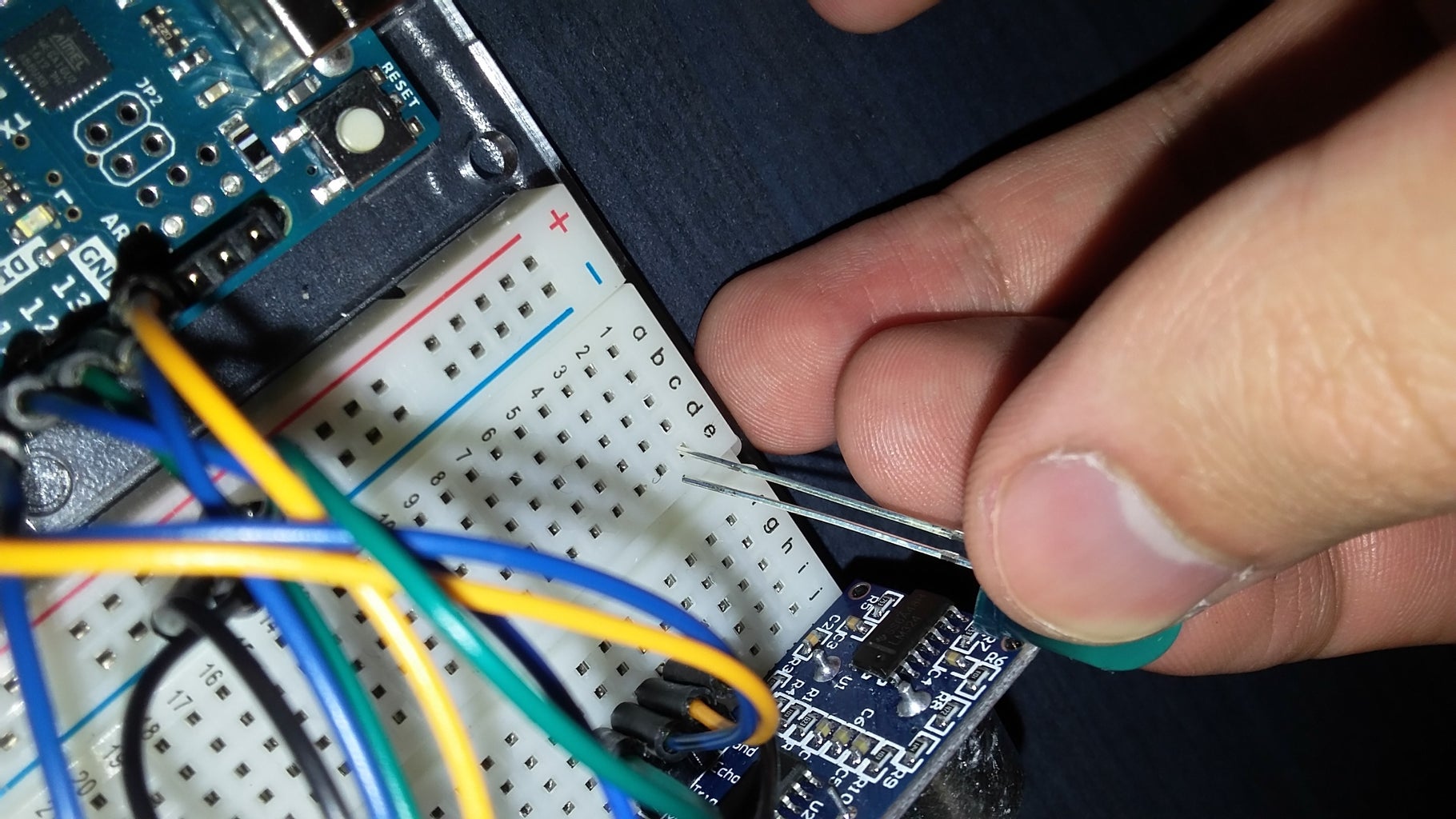
Step 4: Get the UID Information From the RFID Tag And/or Card


With the RFID Reader wired up, you will need to use it to find the UID information of the tag/card you will be using to set the alarm, as this information will need to be updated in the code in order for the alarm to function properly.
Now you can skip this if the UID is already provided for you, but if you do not know the UID of the tag/card you are using, do the following:
- Open the Arduino IDE.
- Click on 'File' in the toolbar, go to 'Examples', scroll down to the 'MFRC522' (this is the RFID Library you added earlier), and select 'DumpInfo'. This will open an example sketch that will read the contents of a tag/card that is flashed in-front of the RFID Reader and dump its contents.
- Plug in your UNO to your computer. Normally, it should automatically install and be ready-to-go but if you experience connection problems (or using the ZIP Version), follow the instructions at this link to do a manual installation: https://www.arduino.cc/en/Guide/ArduinoUno#toc3
- Click on the 'Upload' button (ie. the circle with an arrow pointing right) to load the example sketch on to the UNO. You should now be able to scan in tags/cards with the RFID Reader now.
- Open the Serial Monitor by either clicking the square icon at the top-right of the sketch window or by going to 'Tools' and selecting 'Serial Monitor'.
- Wave your tag or card in-front of the RFID Reader. This information will be then dumped to the Serial Monitor. Ignore the timeout errors as this is not serious and will happen if you pull the tag/card away too quickly.
- In the Serial Monitor, locate the dumped UID, and write down this information. You may have to scroll through the Serial Monitor to find it.
When you have the UID recorded somewhere, you can now forget about the example sketch, and move on with the rest of the alarm.
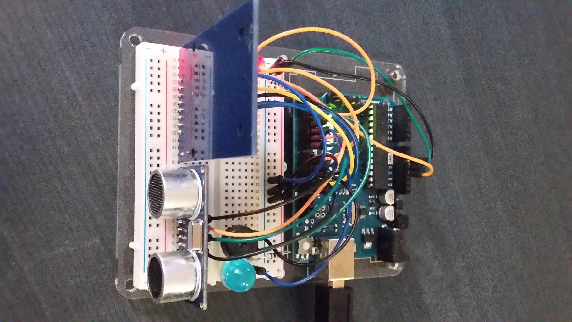
Step 5: Wire Up the HC-SR04 Ultrasonic Sensor
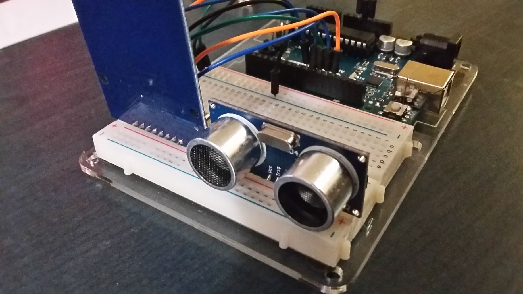

Now is the time to setup the Ultrasonic Sensor which will be used to detect objects that trigger the alarm:
- Unplug the UNO from your computer. Right now, the UNO is running the example code from earlier, so attempting to add new components while its running might corrupt it and prevent the UNO from working properly, even when new code is uploaded.
- Like with the RFID Reader, plug in the sensor vertically into the breadboard.
- Connect wires from each of the following points on the Ultrasonic Sensor to these Digital Pins on the UNO:
- GND => Negative Point on the power rail
- ECHO => Digital Pin 7
- TRIG => Digital Pin 6
- VCC => Positive Point on the power rail
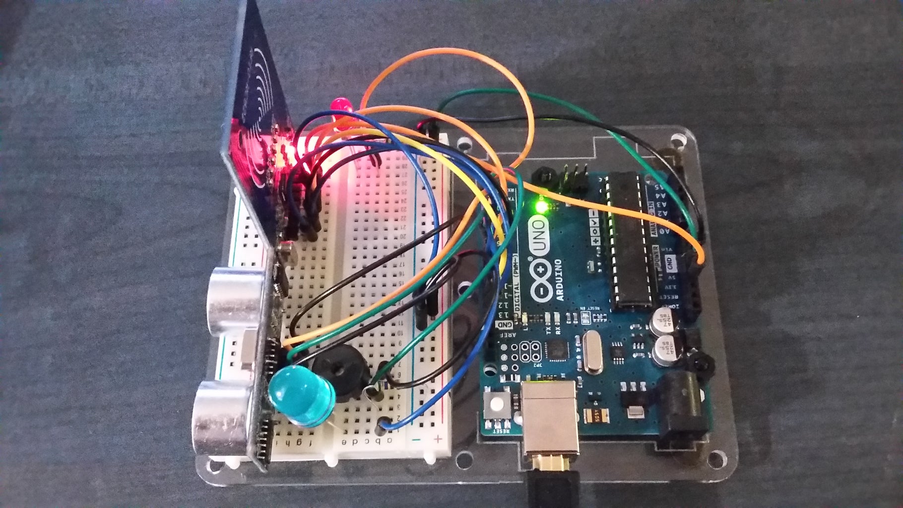
Step 6: Wire Up the LEDs and Buzzer


Now all that's left is to connect the LEDs, which will act as both part of the alarm and a visual indicator as to the alarm's activation status, and the Piezo Buzzer.
First up are the LEDs, starting with the main alarm LED:
- Place the LED vertically in an open space on the breadboard. Remember that the longer end of the LED is the positive and the shorter is the negative.
- Connect a wire from the positive end of the LED to Digital Pin 5 on the UNO.
- Then connect one 270 Ω Resistor between the negative end of the LED and a negative point on the power strip, ensuring that the side with the brown stripe is connected to the LED, as placing it backwards will block the current.
Repeat these steps for the indicator LED, but connecting the wire from the positive end to Digital Pin 2 on the UNO.
Now to connect the Buzzer:
- Place the Buzzer on an open space on the breadboard. Unlike the LEDs, there is no explicit positive or negative end, so just ensure that it is placed vertically.
- Connect one wire from one end of the Buzzer to Digital Pin 4 on the UNO.
- Then connect another wire from the other end of the Buzzer to a negative point on the breadboard's power strip.
Now you have a flashing LED and Buzzer which will act as your alarm and a second LED which will indicate when the alarm is active or not.
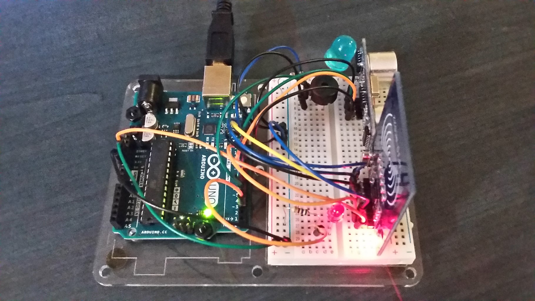
Step 7: Add the Alarm's Code to the Arduino


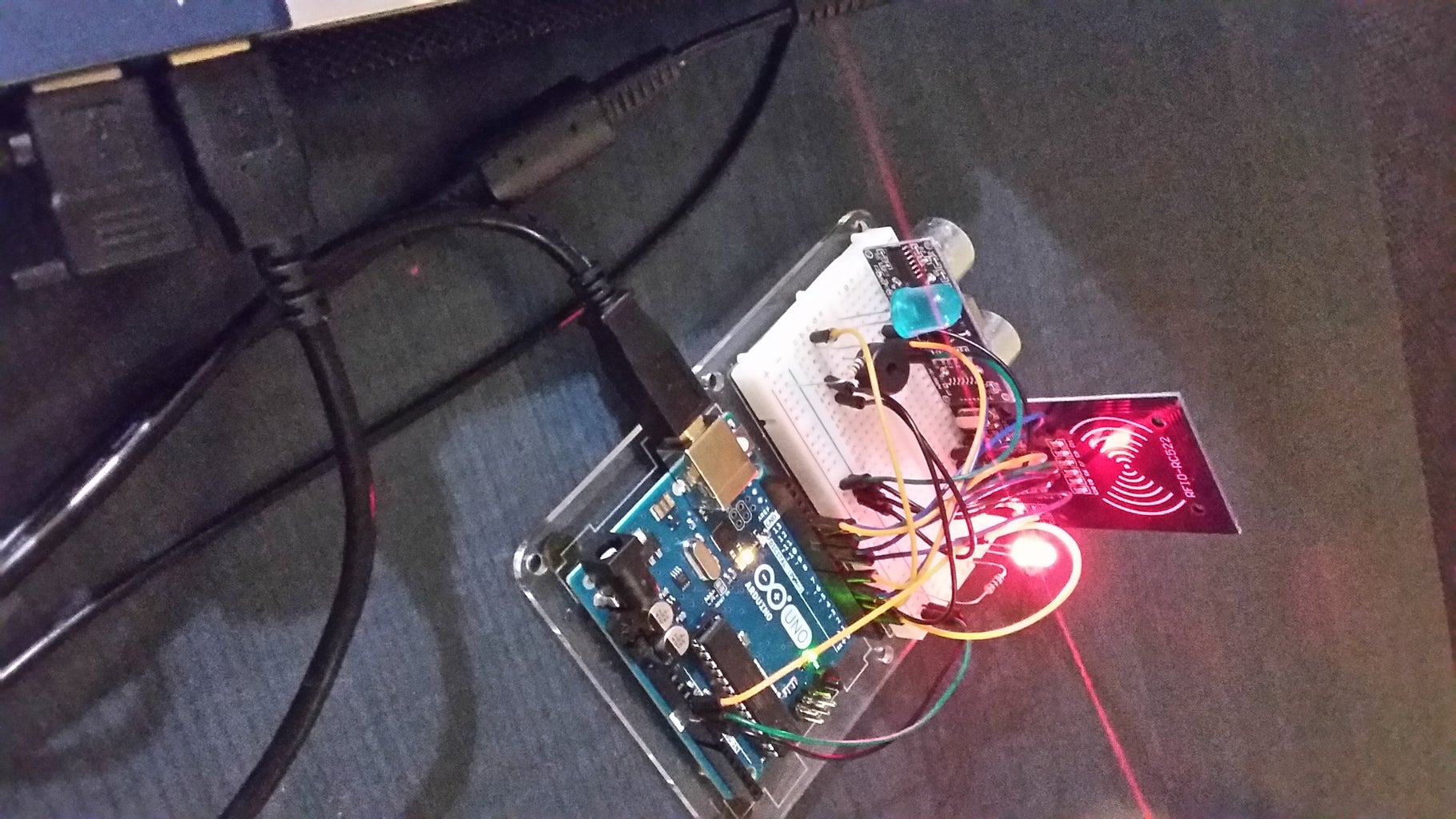

Now for the final part, which is to load the new code onto the UNO that will run all of the components together as a whole alarm system:
- Download one of the attached INO files to a spot where it is easily accessible. The 'EX' Version contains longer, more descriptive comments explaining how the code works if you wish to learn more or make any modifications, while the other contains the same code with minimal commenting for easier reading.
- Open the Audrino Software IDE.
- Go to 'File' and select 'Open'.
- Navigate to the INO file you just downloaded, select it and click the 'Open' button.
- Near the top of the code, locate the String 'targetUID', and change the default UID with the one you recorded earlier.
- Ensure that you've installed the RFID Library; If you haven't, return to Step 2.
- Reconnect the UNO to your computer.
- Like with the example sketch, hit the 'Upload' button at the top-left corner. If you've install all the necessary libraries and wired the components as previously outlined, the code should compile and upload successfully.
That's it! You now have a working Arduino Ultrasonic Alarm. Open the Serial Monitor to see the distances being recorded and have fun!

