

Introduction: Arduino Uno Midi Fighter

This instructable was created in fulfillment of the project requirement of the Makecourse at the University of South Florida (www.makecourse.com)
Based on the popular MidiFighter by DJ Techtools, this homemade Arduino powered Musical Instrument Digital Interface (MIDI) controller can be used as a MIDI device across any Digital Audio Workstation (DAW) software. A MIDI controller can send and receive MIDI messages from a computer and can be used to directly control of whichever software is being used. Additionally, the controls on a MIDI controller are fully customizable -- meaning that each individual button, slider and knob can be mapped to any function in a DAW. For example, pressing a button can play a specific note or be programmed to toggle the tempo of your audio project.
https://github.com/jdtar/Arduino-Midi-Controller
Step 1: Materials
Below is a list of materials and tools used in this project.
Arduino Uno
Breadboard
4051/4067 Multiplexer
Jumper wires
Extra Wire
2x 10k ohm linear slide potentiometers
16x Sanwa 24mm buttons
Heat Shrink
Soldering Iron
Razor blade
4.7 kΩ resistor
Acrylic Sheet (for lid)
Housing for buttons and Arduino
3-D Printer
Laser Cutter
Step 2: Design
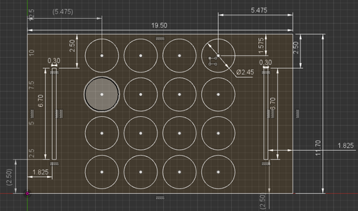
I was already provided the housing for my MIDI controller prior to starting the project, so I mocked up a sketch for the lid in order to visualize where everything was to be placed. I knew I wanted at least 16 buttons and a couple potentiometers as a feature so I attempted to space out the components as evenly as possible.
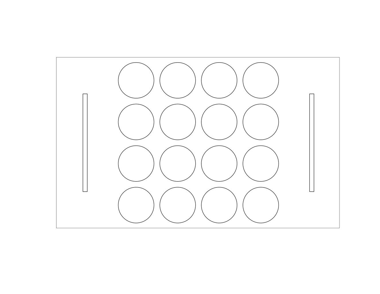
After drawing up the layout for the lid, I exported the file as a 1:1 PDF and sent it to a laser cutter to cut a sheet of acrylic. For screw holes, I marked where I wanted the holes to be with marker and melted the acrylic with a hot filament.
Attached is the 1:1 PDF which can be printed out as a 1:1 and cut with power tools if a laser cutter isn't available.
Attachments

Step 3: Construction and Wiring


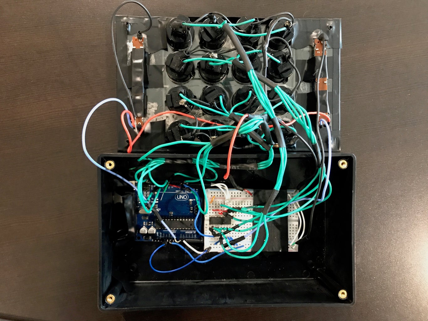
After cutting cutting the acrylic, I found out that the acrylic was too thin to sufficiently support all of the components. I then cut out another sheet and glued them together which happened to work perfectly.
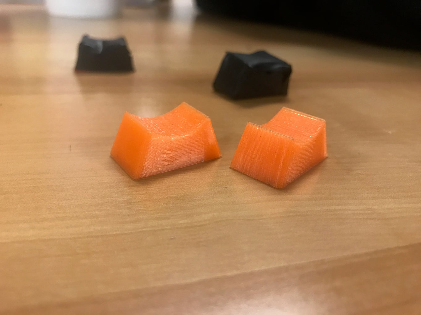
Wiring the components took some trial and error but resulted in the Fritzing sketch attached. I first wired up the ground wires and the 4.7kΩ resistor, soldered and heat shrank the connections on the buttons. Mounting the two slide potentiometers required melting holes for the screws in the acrylic. After the two potentiometers were screwed in, they were wired up to the A0 and A1 analog pins. After the wiring was complete, I remembered that there were no knob caps for my faders so rather than purchase them, I printed some knob caps using a 3-D printer by sketching it out in Autodesk Fusion 360 and exporting to a STL file. De
The Arduino Uno only has 12 available digital input pins but 16 buttons were to be wired up. To compensate for this, I wired up a 74HC4051 Multiplexer on a breadboard which uses 4 digital input pins and enables multiple signals to use a shared line resulting in 8 available digital input pins for a total of 16 digital pins available for use.
Wiring up the buttons to the correct pins was simply of a matter of creating a 4x4 matrix and using that in the code. The tricky part however was that the specific multiplexer purchased had a specific pin layout which the datasheet helped with and also I had a specific note layout in mind when wiring the buttons up which ended up looking a bit like this:
NOTE MATRIX
[ C2 ] [C#2] [ D2 ] [D#2]
[G#2] [ A1 ] [A#2] [ B1 ]
[ E1 ] [ F1 ] [F#1] [ G1 ]
[ C2 ] [C#2] [ D2 ] [D#2]
PIN MATRIX (M = MUX INPUT)
[ 6 ] [ 7 ] [ 8 ] [ 9 ]
[10] [11] [12] [13]
[M0] [M1] [M2] [M3]
[M4] [M5] [M6] [M7]
Attachments

Step 4: Programming

Once the assembly is complete, programming the Arduino is all thats left. The script attached is written in a way such that it's easily customizable.
The beginning of the script includes the MIDI.h library and a controller library borrowed from the Notes and Volts blog which are both included in the zip file for the code. Using the controller library, objects for buttons, potentiometers and multiplexed buttons can be created containing data values which include the note number, control values, note velocity, MIDI channel number, etc. The MIDI.h library enables MIDI I/O communications on the Arduino serial ports which in turn takes the data from the controller objects, converts them to MIDI messages and sends the messages to whichever midi interface is connected.
The void setup portion of the script initializes all channels as off and also initiates a serial connection at 115200 baud, a rate faster than the MIDI signals are being exchanged.
The main loop essentially takes the arrays of buttons and multiplexed buttons and runs a for loop which checks if the button has been pressed or released and sends out the corresponding data bytes to the midi interface. The potentiometer loop checks the position of the potentiometer and sends the corresponding voltage changes back to the midi interface.
Attachments
Step 5: Setup


Once the script was loaded onto the Arduino, the next step is to plug and play. There are a couple steps, however, before it can be used.
On OSX, Apple incorporated a feature to create virtual midi devices which can be accessed through the Audio Midi Setup application on macs. Once the new device has been created, Hairless MIDI can be used to create a serial connection between the Arduino and the new virtual midi device. The serial connection from the Arduino through Hairless MIDI operates at the baud rate defined in the void setup portion of the script and must be set equivalent in the Hairless MIDI preference settings.
For testing purposes I used Midi Monitor to check if the correct data was being sent thought the serial-MIDI connection. Once I determined that all each button sent over the correct data through the correct channels, I set up the MIDI signal to route to Ableton Live 9 as a MIDI Input. In Ableton I was able to map out sliced audio samples to each button and play each sample.


