

Introduction: Arduino Basics No.1 - Photoresistor


In this guide i will show you how yo use the analog input of the Arduino and to control an led according to the values the analog inputs receives.
Step 1: Gathering Materials

What you'll need:
1) Arduino board (here is the one i baught http://www.ebay.com/itm/291113266836?ssPageName=ST... i connected it as an Uno board).
2)LED.
3) Photoresistor ( a photoresistor is a resistor the changes current according to the light, the higher the light level is the lower the resistance).
4) 330 Ω resistor.
5) Arduino cable.
6) Alligator cable.
7) Wires.
Step 2: Building the Chassis

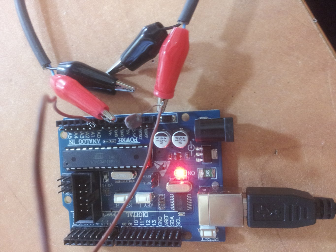


First, connect the photo resistor to the resistor, the resistor goes to Gnd (Ground), from the connection between them connect a wire that goes to Analog input 0.
Now connect the Arduino to the computer.
We now want to see the values that the Arduino reads on A0 (refer to pic No.3).
The purpose of the code is to print (Serial.println) the values the we get from A0.
Notice that as i cover the photoresistor with my finger the values are droping (refer to pic No.4).
Step 3: Values to Analog


Now in order to control the led with our values we want to make sure that we output values in range of from 0 to 255.
In the code (pic No.1) we see the A0 (senespin) reading values, than we make sure that our values are between 32 and 118 anything higher than 118 will become 118 or anything lower than 32 will become 32 (these are the values my arduino reads, if your range is higher or lower change the code according to it).
After the "constrain" command I used the "map" one, this command changes 32 to 255 and 118 to 0, everything between 118 and 32 will scale proportionality between 0 and 255 (notice that as the light level is lower the photoresistor outputs more current the val is lower and the ledval gets higher, and the opposite).
Step 4: Led

Now connect the led to pin 12 and to Gnd and change the code according to picture No.1 the "analogWrite" command outputs a higher current as the ledval gets higher and so the led gets brighter.
As you can see in video No.1 the led gets brighter i shut down my desk lamp.
**Notice that the code are in the next step.
Hope you enjoyed this guide, any comments/ grammar correction will be accepted gladly.
Don't forget to view my other Arduino guides.
Attachments

Step 5: Codes
void setup()//code 1
{
  Serial.begin(9600);
}
void loop()
{
  Serial.println(analogRead(0));
  delay(500);
}
//
//
//
<p>int sens = 0; //code 2<br>void setup()
{
  Serial.begin(9600);</p><p>}
void loop()
{
  int val = analogRead(sens);
  val = constrain( val,32,118);
 int ledval = map(val,32,118,255,0);
 Serial.println(ledval);
 delay(500);
}</p>//
//
//
<p>int led = 12; // code 3<br>int sens = 0;
void setup()
{
  pinMode(led,OUTPUT);
}
void loop()
{
  int val = analogRead(sens);
  val = constrain( val,20,190);
 int ledval = map(val,20,190,255,0);
 analogWrite(led,ledval);

}</p>
Step 6: That's It

Participated in the
Sensors Contest

Participated in the
Epilog Challenge VI


