

Introduction: Measure Li-ion Cell Capacity With an Arduino


I like to use lithium ion cells because they hold a lot more power than "regular" rechargeable cells, and they can be harvested for cheap or free from discarded laptop batteries. They are super handy for flashlights and all kinds of projects. The problem is that, when getting li-ion cells from different sources, you might want to know the capacity of the cells you harvest, especially if you will be using them in series. This project aims to do just that: measure the capacity of a cell using a real load until the cell goes dead.
This instructable was originally published in 2014, but has since been rebooted as I wanted to test another batch of batteries. I re-assembled the circuit, but I added a few features, namely an LCD screen, as well as a cell resistance check.
Before I go on, I'm going to distinguish between “battery” and “cell.” A cell is a single unit of fancy stuff that uses chemicals to store electrical energy. A battery is a collection of cells. So, a D, C, AA, AAA, and an 18650 are all cells. A car battery, laptop battery, or 9 volt are all batteries, because they contain multiple cells.
Step 1: Theory of Operation


This whole step is theory, so if you just want to get it running, skip on to the circuit.
The capacity of a cell is usually given in milliamp hours (mAh). Milliamps are units of current, and hours are units of time, and when we multiply them, we get charge. I*t=Q. So really the capacity of cells is given in Q, the amount of “usable charge” they have in them, or, really, the number of electrons that cell can push through itself in a single discharge cycle.
If we had a constant current, we could just run that current until the cell gets below the minimum voltage, then multiply the current times time, and we would have a rough approximation of capacity (Q=I*T). This is a solid and simple technique, but it will only give rough values, but not a reliably accurate value. This issue comes in when we realize that the current is not likely to stay constant, but rather start off high, then with dropping cell voltage, decrease drastically.
The solution to this conundrum is to use calculus. If we integrate current over time, we can find the exact capacity (Q= ∫ I dt), because if we plot a graph of current vs. time, the area under the curve would represent capacity (milliamps times hours gives milliamp hours). Problem is, I didn't really want to do “proper” integration, so I figured I'd take a shortcut; I used a thing called a Riemann Sum to perform a simple stand in for integration.
In short, we can look at a plot and break it up into a bunch of thin rectangles, calculate the area of each rectangle (width times height), then add all the small areas together. In terms of capacity, we use short time intervals (rectangle width) and multiply each of those with the current (rectangle height) to find a small amount of capacity expended in that time interval. We can just sum up all of the small capacities to find the large capacity.
In the Riemann sum picture (with all the vertical lines), sometimes the q is a little big, and sometimes it is a little small. The idea of a Riemann sum is that the positive errors cancel out the negative errors, and it all washes out to be pretty close.
This Riemann sum is performed until the cell voltage gets below a threshold, then it is stopped, cause that's all the usable charge the cell has (without draining the cell beyond recommend safe limits).
Now as a side note, if we were interested in the total energy contained in the cell, we would need to look at the electrical power expended in the test (which is not the same thing as the charge expended). We could definitely measure this using this same apparatus, by multiplying the voltage by the small q and adding the resulting small e (interval energy expenditure) to a running total E, total cell power. I decided not to do this in the code for this project, but it would not be difficult to implement if you're interested. Otherwise, you can get a rough estimate of the cell energy capacity by taking the mAh rating and multiplying it with the nominal cell voltage, 3.7. (for example, if we had a 1000mAh cell, multiply it with 3.7v to get 3700mWh)
Step 2: Cell Resistance


The main reason for two loads is to be able to measure the cell resistance.
Assuming that the cell is a linear voltage source, all I need to measure the cell resistance is two data points: voltage and current for a given load, then voltage and current for a different load (more or less current). I can then look at how the voltage changed for a given change in current, and the quotient of those two changes gives me the resistance. (remember, one ohm is one volt per amp).
Ohms = -ΔV / ΔI
The method used to measure the cell resistance is to gather many data points, after putting the cell under a random load state out of the four possible states (on on/off off/on off/off on).
After collecting many data points of voltage and current, the program calculates and records the resistance using every data point against every other data point for which neither the voltages nor the currents match. It's sort of like the math handshake problem.
Based on my brief testing, this gives resistance values that can vary by ~10% in the same battery. So it's not great, but it will give you a rough idea.
Step 3: The Circuit


The pictures in this step show how to assemble the cell tester. The text discusses the theory in design of the circuit. You can find a fritzing file at the bottom of this page.
If you have read this instructable before, you will recall that you used to need to have your arduino connected to a computer in order to read the data from the test. This was definitely not ideal, so when I rebuilt this tester, I added an LCD and questioned why I hadn't done that the first time around. You can buy a 16x2 character LCD on ebay for about $5 with shipping included.
The actual test circuit contains two loads and two mosfet switches, to facilitate measuring the cell resistance. If you aren't interested in the cell resistance, you can certainly build the circuit with just one mosfet and load (the code won't mind).
This test circuit uses an N-channel mosfet to switch the current. The best source I have found for large power mosfets is computer power supplies (easy to find: they're on the big heat sinks). Before running this test, read the datasheet for your mosfets and make sure that they can handle a minimum of about 1A, unless you use a lower current load. Also, make sure that the "gate-source threshold voltage" is less than 5v. This is the voltage that the mosfet requires to turn on, and we can only give it 5v using the arduino. Lastly, you may want to put the mosfets on a heat sink.
The method we use to measure the current is to use a shunt resistor. We measure the voltage at both sides of the resistor in order to calculate the current. Ohm's law says V=I*R, or I=V/R (the current through the resistor is the voltage difference across it divided by the value of the resistor).
The value of the shunt resistor should be anywhere from 4 ohms down, but for a ~1A load, a good rule of thumb is that the power rating of the shunt resistor should be roughly four times the current, or about a 4w resistor at the smallest. This is in order to keep the resistor cool. As Domints has pointed out in the comments, if the resistor gets very hot, its value changes and your capacity readings are no longer accurate.
The load that I used in this circuit is a car brake light bulb (I am using the two filaments as the two loads). Between that and the shunt resistor, about one amp gets pulled during the test, and that's just about right for what I want to do. The Peukert effect discusses the effect of different current loads on a cell's capacity.
Be careful: connection A and B need to go to analog inputs. If you connect them to a digital pin, you will short the current lithium ion cell straight through your arduino. Bad times.
The schematic and breadboard layout can be found here, in the fritzing file (fzz).
Step 4: The Code


Download the code here.
The code in this project goes through 10 possible states, always starting after a reset at state 0, in which the cell voltage is measured and, depending on the voltage, the program goes to one of three possible next states.
State 1 occurs when the voltage is below 1v, and the program assumes that the battery holder is empty. It prompts for a new battery then reset. once the cell voltage goes over 1v, the program goes to state 2.
State 2 occurs when the tester started with no cell but now has a cell installed. The program displays the cell voltage and prompts for a reset.
State 3 occurs when the program started with a cell voltage between 1 and the minimum voltage to begin a test, in other words, a weak cell. The cell voltage is displayed along with an advisement of a weak battery.
State 4 occurs when the program began and the cell voltage was high enough to begin a test. In this state, the loads are turned on until the voltage gets below the threshold to check the resistance.
State 5 is the state in which the resistance is checked. The current and voltage are measured, then oneof the loads is turned off and back on after recording the two voltage/current values. The resistance is calculated from those two values with different load currents.
State 6 occurs right after state 5 finishes checking the resistance, and continues running the capacity check until the cell voltage falls below the minimum cell voltage.
State 7 occurs when the capacity check is complete and the cell is still in place. It displays the test results and the time that the test took.
State 8 occurs when the battery is removed from the tester after a test run. The capacity and resistance are still displayed, but not the time.
State 9 occurs when a new cell has been inserted. The capacity is still shown until a reset.
So, how should you edit this code to make it work for your specific circuit? The only things you should need to change are the pin numbers and the resistor value. They are in the following constants:
#define SHUNTRES 0.62
#define VIN A1
#define SHUNT A0
#define GATE1 0
#define GATE2 1
Something that a few of you have commented about is an inaccurate reference voltage. What if your 5v pin measures 4.6 volts? There is also a constant to take care of that. Measure the 5v reference pin with a multimeter, then put that votlage in the constant below:
#define VOLTREF 4.6
If you are powering the arduino from a computer's USB port, the voltage should be right at 5v (and there's no need to check it, unless you're the suspicious type). If you are using a power supply into your Arduino's voltage regulator (barrel plug), the you might need to check it, but it should be consistent. If you're using a USB charger to power it, you should check the voltage of every different one you'll use, cause they can vary a lot.
Step 5: Share Your Results!
So, this project is all well and good, but let's say you just want to know the capacity of your cell without building the thing. Well, I have started a list of batteries, identifiable by color and model number, and you can view it here.
If you have built a capacity meter and would like to contribute to this list, please message me and I'll add you as an editor.
Step 6: Put It Together and Measure


Ok, so once you build your circuit, throw your code on the arduino and you should be good to go!
The cells should be fully charged before you start a test, so you can know what their full capacity is. Connect a cell, and to start the test, either push your arduino reset button, or power cycle the arduino.
Once the test is complete, the screen will display "done" along with the time, cell resistance, and capacity.
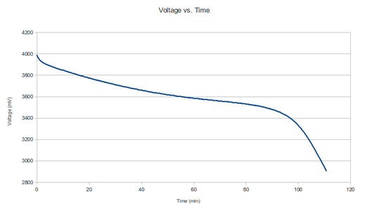
I made a graph of voltage vs time for a test cycle, and it has some pretty interesting features. The beginning shows a sharp drop in voltage, but it levels off to a pretty much linear voltage decline, until it gets down to about 3300 mV. At that point, it starts to drop off steeper and steeper. This shows why discharging a li-ion cell below 2.9v really won't get you much more usable power. The battery starts strong and stays strong... then it's done.
This test apparatus can be used on different cells than just li-ion. You need to adjust the voltage constants of course, and you need to make sure you don't feed more than 5v to the analog pin, as that's the maximum it can read. A voltage divider would be one possible way to measure the voltage of higher voltage applications (for example, a 12v lead acid battery).
So far I have observed something about my cells: they seem to mostly be manufactured to be roughly 1000 or 2000 mAH. I had one get up to 3400 mAH, which is pretty impressive for just a little 18650. Also, most of the cells that come with really cheap LED flashlights tend to have horrible capacity. But that's no surprise.

Participated in the
Arduino Contest


