

Introduction: Arduino From Scratch - Digital Thermometer


More by the author:


About: I live in Michigan, USA. I've been a Maker hobbyist for many years. It's fun to be Geeky.
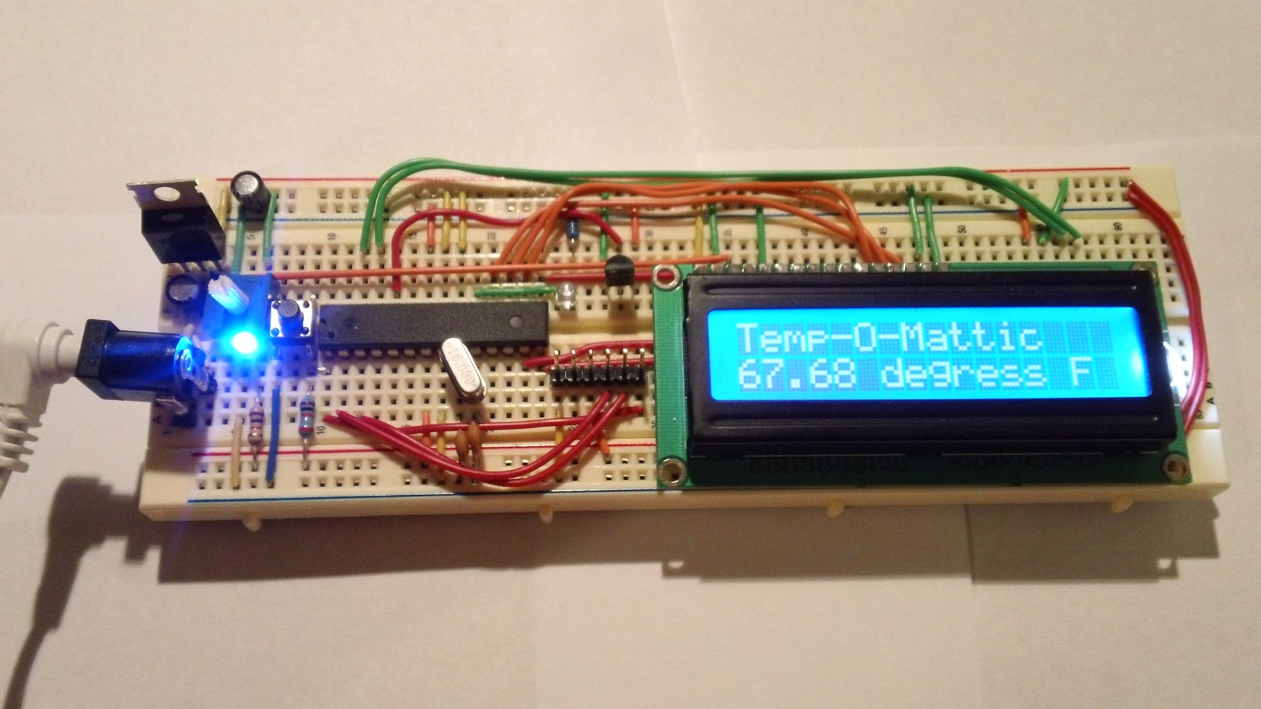
I have loved making projects with Arduinos, but at $30 a piece your projects can get expensive. So I want to show you how you can make your own Arduino from scratch and save money doing it. Make your own Arduino for around $8. For this instructable I show you how to make one on a breadboard and with it make a digital thermometer.
For more videos like these and other DIY projects, click here.
Step 1: Parts You Need for the Arduino:

- Full Size Breadboard ($8 adafruit.com)
- 22 AWG Wire or jumper wires ($6 adafruit.com)
- 1 - 7805 Voltage Regulator ($0.18 taydaelectronics.com)
- 2 - LEDs ($0.02 each taydaelectronics.com)
- 2 - 220 Ohm Resistors ($0.10 each taydaelectronics.com)
- 1 - 10k Ohm Resistor ($0.10 taydaelectronics.com)
- 2 - 10 uF Capacitors ($0.01 each taydaelectronics.com)
- 1 - 16 MHz Clock Crystal ($0.07 taydaelectronics.com)
- 2 - 22 pF Capacitors ($0.10 for pack of 10 taydaelectronics.com)
- 1 - Small Momentary Normally Open "off" Button ($0.05 taydaelectronics.com)
- 1 - Breadboard-friendly 2.1mm DC barrel jack and 9V Wall Wort with 2.1mm Plug (2.1mm jack $0.95 adafruit.com)
- 1 - ATMega328 with Bootloader ($6 adafruit.com or cheaper other places if you can add your own bootloader)
Assuming you have a breadboard, wire, and a way to program (see step 4) the Arduino parts cost a total of $7.71 +shipping.
Step 2: More Power Captain!


Connecting the power source:
Plug in the 2.1mm barrel jack on the side of the breadboard like in the picture and add jumper wires going across the middle. (instead of the barrel jack and wall wort you can use a wired up 9v battery)
Add the 7805 power regulator and the lines to power the board. It's input from the external power supply goes in on the left, ground is in the middle and the 5V output is on the right (when facing the front of the regulator). Add power OUT and ground wires that connect to the right and left rails of the breadboard.
Also, add a 10uF capacitor between the IN of the regulator and the ground (between the plug and 7805) as well as a 10uF capacitor on the right rail between power and ground. The silver strip on the capacitor signifies the ground leg.
Add power and ground wires at the bottom of your board connecting each rail. So now the bottom and top have power and ground. (see pic)
Now you are going to add the power "on" indicator. Add an LED and a 220-ohm resistor on the left side of your board behind the barrel plug. An LED attached to power like this is a great troubleshooting trick. You'll always know when your board is being powered as well as quickly know if your board is being shorted.
Plug in the power to turn it on and see if your LED lights up. If it does you are good to go for the next step. If not, check all the steps and cross reference with the pictures to find any errors.
Time for the "All Mighty Arduino!!!"
Step 3: Brainzzz!


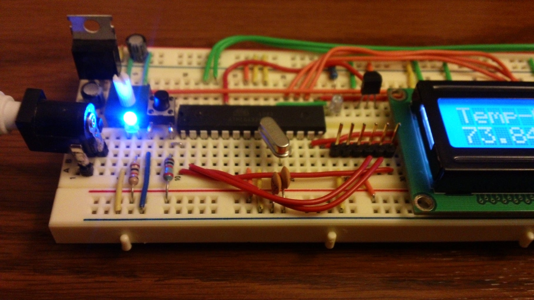
It's Arduino Time (see pictures for more details)
Take a moment to review the Pin Mapping (picture) of the Atmega. (Atmega168 and 328 have the same pin map.) When "pin" is mentioned it is in reference to the chip's pin not digital pin or analog pin.
Add the small tactile switch so that you can reset the Arduino whenever you'd like. Add the switch just above the top of the Atmega chip crossing the gap in the breadboard. Then, add a wire from the bottom left leg of the switch to the RESET pin of the Atmega chip and a wire from the top left leg of the switch to ground. Connecting a 10k ohm pullup resistor to +5V from the RESET pin
Connect to power(5v) and ground.
Pin 7 - Vcc - 5v
Pin 8 - GND
Pin 22 - GND
Pin 21 - AREF - 5v
Pin 20 - AVcc - 5v
Add a 16 MHz external clock between pin 9 and 10, and add two 22pF capacitors running to ground from each of those pins.
Now your Arduino should be all set, but lets test it. First add an LED just down from the Atmega and run wire from it's positve side to pin 19. Add a 220ohm resister from the LED's ground side to the ground rail.
Now let's make that LED Blink.
Step 4: Programing...


There are a few ways to program this chip.
1. If you have another Adruino you can use it to program your chip by carefully swapping out the chip it came with. OR
2. You can buy a "FTDI friend' from adafruit.com $14.75 That is what I used.
If you aren't using this go the to next step.
It comes with a 6 pin row. Put this in (see pic) and connect as follows going left to right.
(Note: don't plug in both the FTDI friend and the external power at the same time)
Using one the these 2 methods go ahead and program the "Blink" sketch that comes with the software.
If your LED starts blinking away, you know everything is good and it's time to move on.
If you want to make the digital thermometer than you can program this sketch now.
/* This sketch is orginally from Ladyada.com.
It has been modified by Matt Jenkins 10/27/2011
*/
// include the library code:
#include <LiquidCrystal.h>
// initialize the library with the numbers of the interface pins
LiquidCrystal lcd(7, 8, 9, 10, 11, 12);
//TMP36 Pin Variables
int tempPin = 1; //the analog pin the TMP36's Vout (sense) pin is connected to
//the resolution is 10 mV / degree centigrade with a
//500 mV offset to allow for negative temperatures
int tempReading; // the analog reading from the sensor
void setup(void) {
// set up the LCD's number of columns and rows:
lcd.begin(16, 2);
// Print a message to the LCD.
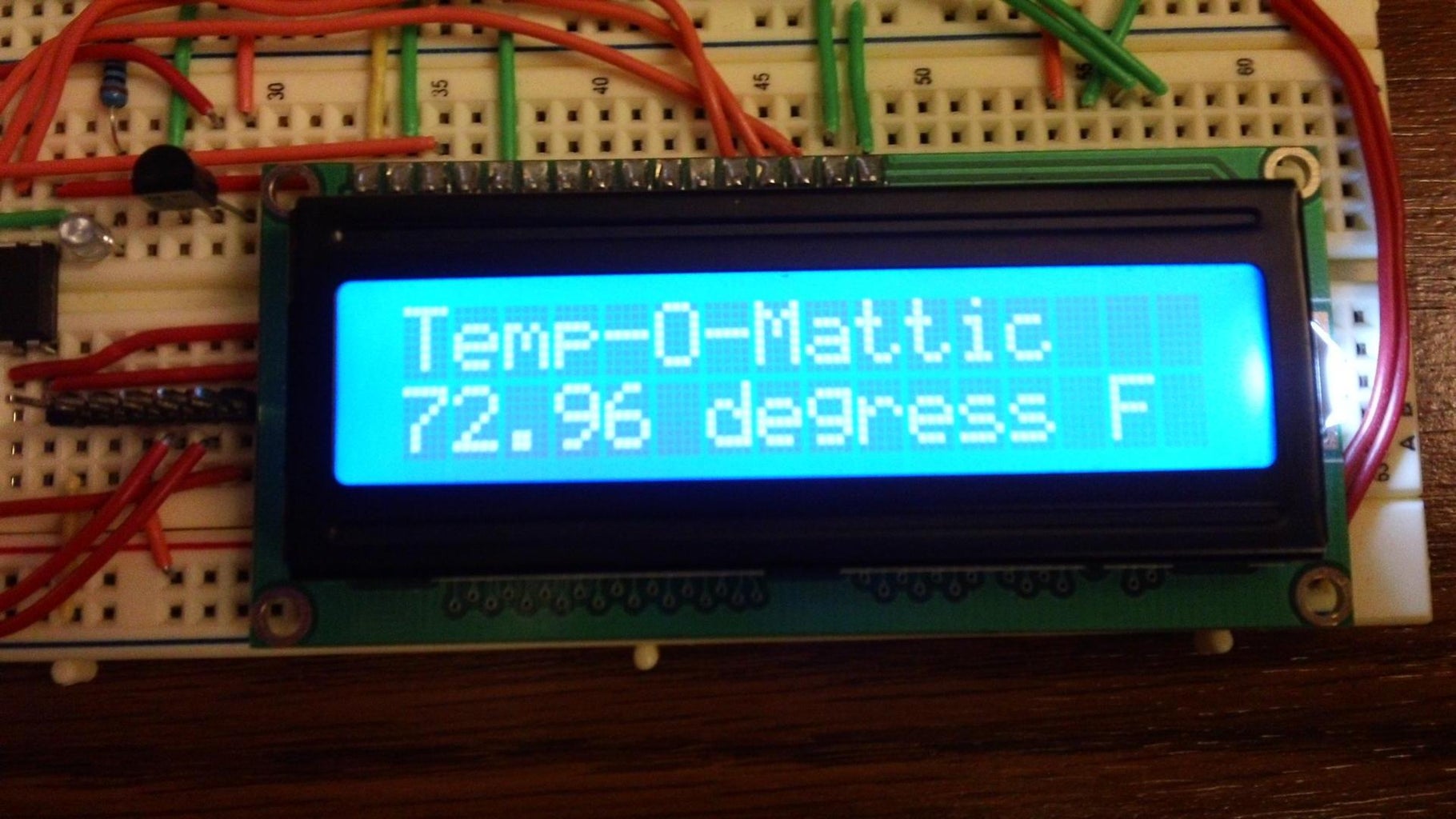
lcd.print("Temp-O-Mattic"); // You can change "Temp-O-Mattic" to something else like "The Temp is..."
}
void loop(void) {
tempReading = analogRead(tempPin);
// converting that reading to voltage
float voltage = tempReading * 5.0;
voltage /= 1024.0;
float temperatureC = (voltage - 0.5) * 100 ; //converting from 10 mv per degree wit 500 mV offset
//to degrees ((volatge - 500mV) times 100)
// set the cursor to column 0, line 1
// (note: line 1 is the second row, since counting begins with 0):
lcd.setCursor(0, 1);
// now convert to Fahrenheit
float temperatureF = (temperatureC * 9.0 / 5.0) + 32.0;
lcd.print(temperatureF); //If you want C and not F just change "temperatureF" to "temperatureC"
lcd.println(" degress F "); //You can change F to C
delay(1000);
}
1. If you have another Adruino you can use it to program your chip by carefully swapping out the chip it came with. OR
2. You can buy a "FTDI friend' from adafruit.com $14.75 That is what I used.
If you aren't using this go the to next step.
It comes with a 6 pin row. Put this in (see pic) and connect as follows going left to right.
- To ground
- Not used
- To 5v
- To pin 2
- To pin 3
- To pin 1
(Note: don't plug in both the FTDI friend and the external power at the same time)
Using one the these 2 methods go ahead and program the "Blink" sketch that comes with the software.
If your LED starts blinking away, you know everything is good and it's time to move on.
If you want to make the digital thermometer than you can program this sketch now.
/* This sketch is orginally from Ladyada.com.
It has been modified by Matt Jenkins 10/27/2011
*/
// include the library code:
#include <LiquidCrystal.h>
// initialize the library with the numbers of the interface pins
LiquidCrystal lcd(7, 8, 9, 10, 11, 12);
//TMP36 Pin Variables
int tempPin = 1; //the analog pin the TMP36's Vout (sense) pin is connected to
//the resolution is 10 mV / degree centigrade with a
//500 mV offset to allow for negative temperatures
int tempReading; // the analog reading from the sensor
void setup(void) {
// set up the LCD's number of columns and rows:
lcd.begin(16, 2);
// Print a message to the LCD.
lcd.print("Temp-O-Mattic"); // You can change "Temp-O-Mattic" to something else like "The Temp is..."
}
void loop(void) {
tempReading = analogRead(tempPin);
// converting that reading to voltage
float voltage = tempReading * 5.0;
voltage /= 1024.0;
float temperatureC = (voltage - 0.5) * 100 ; //converting from 10 mv per degree wit 500 mV offset
//to degrees ((volatge - 500mV) times 100)
// set the cursor to column 0, line 1
// (note: line 1 is the second row, since counting begins with 0):
lcd.setCursor(0, 1);
// now convert to Fahrenheit
float temperatureF = (temperatureC * 9.0 / 5.0) + 32.0;
lcd.print(temperatureF); //If you want C and not F just change "temperatureF" to "temperatureC"
lcd.println(" degress F "); //You can change F to C
delay(1000);
}
Step 5: Connect the Temp Sensor


Install the TMP36 (see pic)
Plug in the TMP36 sensor so the 3 pins each have their own collum in the breadboard.
Plug in the TMP36 sensor so the 3 pins each have their own collum in the breadboard.
- Wire the first pin to 5v
- Wire the second (middle) pin to pin 24 (analog pin 1) on the Atmega
- Wire the third pin to ground
Step 6: Add the LCD Display


I recommend you buy your LCD from Adafruit.com. You can get the same one I show you for $10 and it comes with a necessary contrast potentiometer and a strip of header pins that need to be soldered on. They have other cool ones too.
First plug in the potentiometer. I have mine down by the power plug. There are 3 pins. The pin on one end goes to 5v and the other end goes to ground. The middle pin goes to pin 3 on the LCD.
There are 16 pins on the LCD. "1" is the upper left corner and the others go down the top toward the middle of the board. You need to wire it in like so.
Pin 1 - Ground
Pin 2 - 5v
Pin 3 - Middle pin of the potentiometer
Pin 4 - Atmega pin 13 (digital pin 7)
Pin 5 - Ground
Pin 6 - Atmega pin 14 (digital pin 8)
Pin 7 - not used
Pin 8 - not used
Pin 9 - not used
Pin 10 - not used
Pin 11 - Atmega pin 15 (digital pin 9)
Pin 12 - Atemga pin 16 (digital pin 10)
Pin 13 - Atmega pin 17 (digital pin 11)
Pin 14 - Atmega pin 18 (digital pin 12)
Pin 15 - 5v
Pin 16 - Ground
If you had already programed the chip for the "Temp-O-Mattic" then just plug in the power and it should be working. If you didn't notice you can change the words on the LCD from the program.
Step 7: Troubleshooting/More Info

If it's not working there are a few things you can try and check.
- Is your "on" light lit? If not make sure the power it plugged in, the caps are in the right way (silver line means ground), the 7805 is in the right way, and you have the positive and ground wired right coming from the barrel jack.
- Did the "Blink" sketch work? If not, check you have all the parts in. Compare the pictures to yours to see if anything is different.
- Is the LCD lit? If not, your did not wire it in correctly.
- Are you seeing a message on the LCD? If not, turn the contrast pot. If that doesn't work, check your connections, and reprogram the sketch.
- You can leave questions in the comments below and I'll try my best to answer them.
- Check out these awesome websites.
TMP36 Tutorial http://www.ladyada.net/learn/sensors/tmp36.html
LCD Tutorial http://www.ladyada.net/learn/lcd/charlcd.html
Breadboard Arduino http://arduino.cc/en/Main/Standalone
Arduino Software Download http://arduino.cc/en/Main/Software
Buy Stuff:
www.adafruit.com
www.sparkfun.com
http://www.taydaelectronics.com
