

Introduction: Arduino-powered Timer for Cup Stacking
Hello! This is my very first Instructable, but I'm so glad of what I've built that I need to share it with the community that gave me all the hints and the motivation I needed.
This project has born after my children asked me over and over to elapse their performance in the Cup Stacking (but I've found it can be useful also for Rubik’s cube or other hand-based tasks). The rules are very easy: measure time from the moment when one hand leaves the table to the moment both hands are placed back on the table. And please, remember the best time achieved :-)
After thinking a while about it, I searched on the Internet about some capacity switch for Arduino and I stumbled on the Capacitive Sensing Library, which has been designed exactly for this goal. I then decided to realize the timer with the Arduino kit I have at home.
I apologize for my english, I hope it’s good enough for you to understand.
Step 1: What You Need

No need for special hardware or tools, in the picture you can see the list of material I used for this project:
- Arduino UNO (or equivalent)
- Breadboard
- 1602 LCD display (2 rows x 16 chars, you can do also with the 2004)
- aluminum foil (the one you use in the kitchen)
- 2 plastic envelopes
- wires and resistors
I've tried to keep stuff as simple as possible: however, a minimum knowledge of Arduino platform is needed, mainly to install the Capacity Sensing library and test the sensors.
Ready to build? Go on…
Step 2: Build the Sensors


The first thing to do is to build the capacitive sensors: cut two pieces of aluminum foil, put each of them in a plastic envelop and fix a wire to it (I have used a crocodile clip wire, but a normal copper wire fixed with some self stick tape should be fine as well).
After that, it's better to test it using the Capacitive Sensing Library test program, just to understand the values that comes from reading the sensor: I've found that, in my case, a value greater that 200 it's enough to state that an hand has been put on the sensor.
To test the sensor:
- open the Capacitive Sensing Library page
- scroll down to the Installation section and follow the instruction to install it
- build a sketch and run the Demo Sketch described in the same page just below
Step 3: Build the Circuit
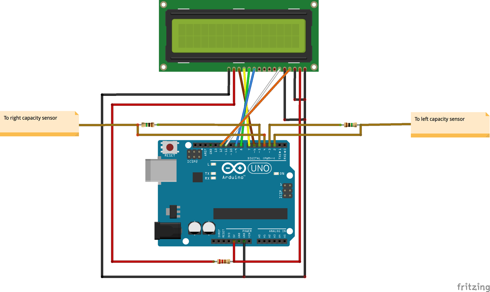


The image shows the schema of the circuit, designed using Fritzing. I tried to keep the same color for the wires as I did in the schema to simplify the task of building it.
The circuit itself is a little bit messy, mainly because of the 2x16 display, which requires a lot of wires: I don't own an I2C display adapter, this would reduce a lot the number of wires required. If you want or need, you can put a 10k ohm potentiometer to trim the display luminosity (please refer to Arduino Liquid Crystal library examples for reference).
Also, I decided to use breadboard and wires, but one of the major future improvements would be to design and build a PCB and to solder all the components.
Step 4: Upload the Firmware
The Arduino code to drive the timer is attached here: you have just to download, unzip and flash it to Arduino (of course, you need to install the Capacity Sensing library, if you didn't it yet).
Just a couple of words about it: I found a lot easier to implement it as a finite-state machine, on which each action on the sensors can change the state. It has also been easy to extend its behavior, by simply add a new state when needed.
I'm pretty new to Arduino, so the code should be easy to understand: I've filled in with comments to better explain what each single part does.
Attachments

Step 5: Final Test
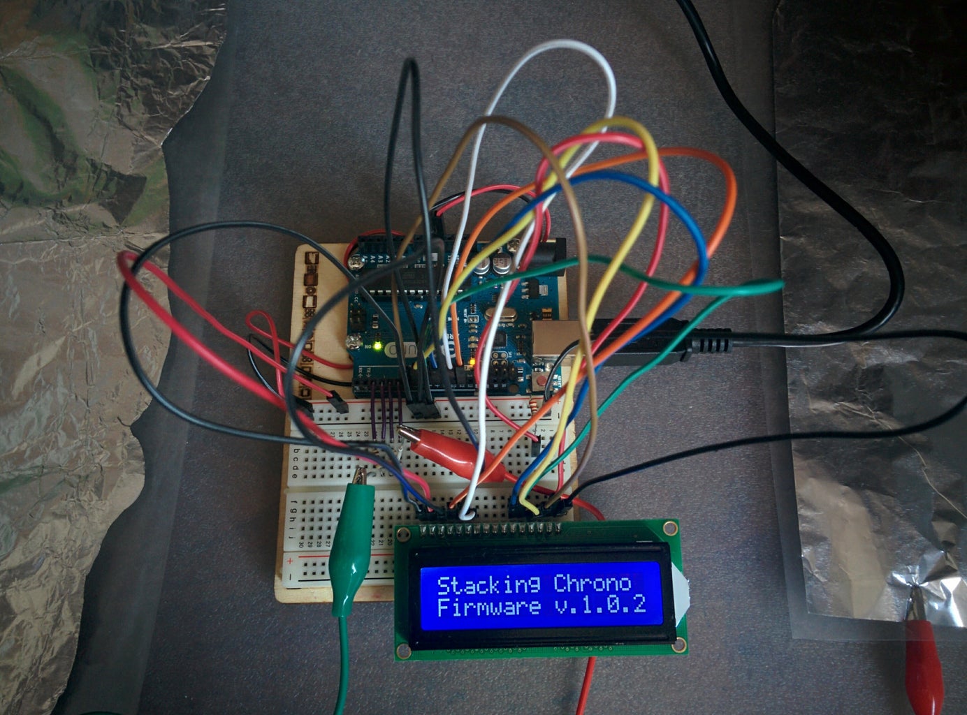
That's it, time to test your timer. Simply power it on with an USB battery charger or using your PC or plugging a 9V power supply on the Arduino power input (please refer to Arduino docs for details), put your hands on both the sensors and wait until the timer is ready to start. When your hands (actually, just one it's enough) leave the sensors, the timer starts; it stops when both are back in place.
If the time you scored is better (shorter) than the previous best one, you'll see it recorded on the first row.
And that's it, pretty simple but effective!
Step 6: Future Improvements
This project has been done for fun, so I'm not planning to improve it. Anyway, I'm sharing with you some idea to make it better, if you dare:
- add a buzzer to play some sound when going ready, started and stopped
- add a button to reset the best time recorded (can be the capacity sensor itself)
- add an history of the last 20 recorded times and some interface to display it (can be the capacity sensor itself)
- use an I2C adapter for the display
- design & built a PCB to solder all the components on it
- build a case for the components
- find something better for the sensors, like a plastic colored cover
That's it, thanks so much for reading and happy making!


