

Introduction: Assembling AM Radio Receiver Kit


I love assembling different electronic kits. I am fascinated by the radios. Months ago I found a cheap AM radio receiver kit in Internet. I ordered it and after the standard waiting of around a month it came. The kit is DIY seven transistor superheterodyne AM receiver. Assembling such radios can be tricky - two main problems have to be solved:
- Setting the proper operatimgl points for the transistors
- Tuning the resonance circuits
In this specific case it appeared another complication - linguistic. The assembling instruction is written only in Chinese. If you decide to build such radio - this instructable will be useful - it shows how to solve this problem.
Lets start....
Step 1: What Is Inside...

The kit contains all the necessary parts to build the radio. The PCB is single sided with white silkscreen element labels and drawings on the top side. In the kit are few resistors more included.
Two remarks:
- Be careful when placing components - there can be difference between the labes on the PCB and the schematic. In my case the transistors VT2 and VT3 were swapped. Re-check the correspondence PCB-schematic
- The ground wire is split. The different parts are connected through the coil shields. To make some test may be would be needed to bridge the different GND parts temporary with some wires.
Step 2: Assembling...(Output Stage)


Building a radio receiver usually starts from the output to the input. In this case it is easier to check the functionality of the different stages and to continue further adding more complexity.
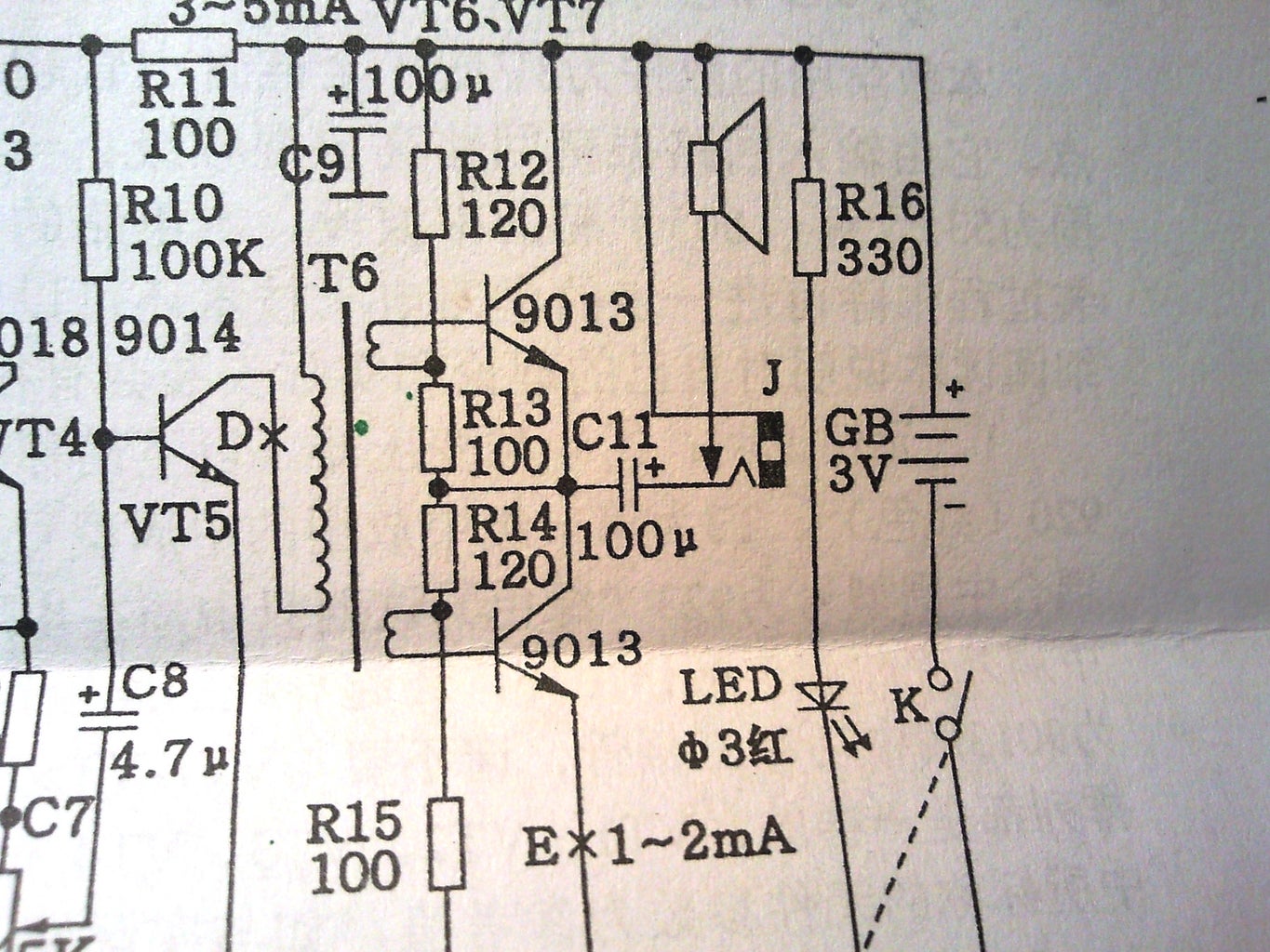
The output stage is class A based on two NPN 9013 transistors, Their DC OP are set by the resistors R12, R13, R14, R15. Both transistors are driven by the audio transformer T6. I would suggest before soldering of each transistor to check it functionality, its type and beta. The audio transformer has 3 windings. Check with ohmmeter at which pins they are connected and orient the transformer in the right way, Notice that the current which has to flow through the amplifier stage is written on the nets or at the top of the schematics in line with the corresponding transistor,
Step 3: Assembling...(Output Stage) - Continuation


There are special points on the PCB, where the current can be measured. They are marked with letters. In the case of the output stage - the letter "E" points the place where the current should be checked. You apply 3V power supply and with ampere meter measure the flowing DC current. It must be in the limits written in the schematic. (In my case the current was a little higher, but it is not problem for this type output stage)
Finally you can solder the speaker, short the bridge "E" with solder and supply the board (now it has only the output stage), apply some audio signal and check if it works. You can apply the signal at the bridge labeled with "D".
After that you solder VT5, C8, R10, R11 and the potentiometer. Now you can repeat the audio test applying the signal at the top terminal of the potentiometer. Solder C6, C7, R9.
Step 4: The AM Detector


In the radio the VT4 transistor is connected in a diode configuration. It performs the amplitude detector function. Using transistor in this configuration can work, but better solution is to replace it with the proper device for this function - Germanium Detector diode ( for example 1N34A). Such diodes can ve found cheap in Internet. Advantages - lower capacitance, higher speed and better detecting function.
Step 5: The IF Stage


Now comes the difficult part - The Intermediate Frequency (IF = 455 kHz) stage contains 4 coils marked with different colors. Each must be soldered on the proper pace. How to know which coil where to mount? Each explanation in the assembling instruction is in Chinese!
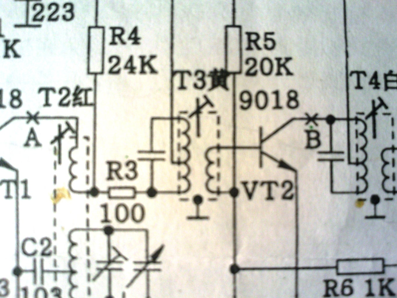
The solution: On the circuit, near each coil is put a Chinese symbol. Logically - it represents the coil color.
But how to decode it. Look in the picture under the PCB drawing. There is a table with 10 numbers and 2 additional percent cells. What is that? - That is the resistor color code. Find in Internet such table and decode which symbol which color represent. On the last photo you can see my decoding:
T2 - red
T3 - yellow
T4 - white
T5 - green.
Step 6: IF Stage


We solder the coils - they perform also ground wire connection.
The next task is to set the OP of the IF stage transistor amplifier VT3. To make it right, the beta must be measured, After that You perform the calculation shown on the last photo and chose standard value for resistor R7 closest to that calculated. Other method - replace R7 with potentiometer and measure the current through bridge "C". The same for the transistor VT2 (replace R5 with potentiometer and measure the current at bridge "B") . Short these bridges after that.
Step 7: RF Stage

The transistor VT1 performs three functions :
- Amplifies the input radio frequency
- Local oscillator
- Mixer - sums and extracts both frequencies - the resulting frequency products are fed to IF filter (T3) and in this way the IF 455 kHz frequency is produced.
The OP of VT1 is set in the way shown on the picture. The beta of the transistor is the input data.
At this moment all devices should be soldered on the PCB.
Step 8: RF Part and Mechanical Works


The antenna coil must be soldered. Be careful to solder the wires at the proper positions. They are numbered. Solder the variable capacitor. Mount the turning wheel. Turn it in the end position and glue the frequency pointer, in the way that it also points to the max or min frequency ( depending in which direction You turned the wheel).
Mount the speaker and the battery contacts. Fix the board with a screw.
Step 9: Adhustments


Now the radio must be tuned. The tuning is performed by rotating the ferromagnetic coil cores. It is better for that purpose to use some nonmagnetic screwdriver. I used a plastic stick, which I sharped. For precise tuning I used a RF signal generator described here. I set to AM with frequency 455 kHz and low signal level. The tuning I started again from the back end in direction the front end. The signal was injected first at the base of VT3. The coil T5 was tuned in the way to hear the best and strongest audio signal from the speaker. After that the coil T4 was tuned applying signal at the base of VT2. T3 was tuned applying signal at point A. The tuning of T2 is more complicated. It is successive approximation and must be performed few times. First we apply an AM frequency corresponding to the highest input frequency (1605 kHz). We rotate the tuning capacitor to the end pointing that frequency. We rotate the small capacitors placed in the variable capacitor until we start to hear the audio signal. After that we turn the variable capacitor at the lowest frequency and apply with the signal generator an AM signal with frequency 535 kHz. We rotate the coil T2 core until we have the best quality audio signal. We repeat this operation until the radio catches both frequencies at both tuning wheel end positions.
That's all Folks. :-)
Thank you for the patience when reading this work.


