

Introduction: Attiny 85 Programming Shield


Attiny 85, my favorite of all the Attinys. They are great because they are inexpensive, super small and still get the job done without having to use a whole Arduino. However I do not like coding them using a bread board. It can take for ever if your a beginner, it may look sloppy and sometimes if the pins are connected wrong it can mess up the little micro-controller. So to solve this I will show you how to make a shield that will fit on to your Arduino that can program your Attinys easily.
I have seen only a couple of Instructables like this before but most use wires going over the top, mine however uses a technique making it look even cleaner than other shields.
With all of this said lets get started!
Step 1: Parts Needed


This circuit is extremely easy to build and requires very cheap parts for the actual shield. Here is what you need:
For the Shield:
1 x Perf-board
1 x 8 pin- IC socket
6 x Male Header pins
Thin gauge wire
For Programming:
1 x Attiny 85
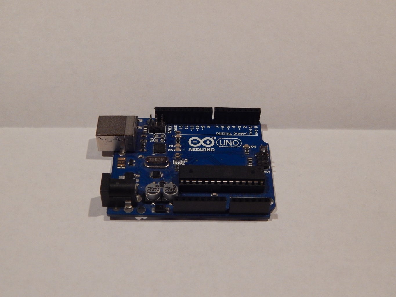
1 x Arduino Uno
Tools Needed:
Soldering Iron
Solder
You may think I am missing the 10 uf capacitor however my Arduino Uno is a newer version so it does not require one. But it would be a very simple addition.
Step 2: Programming Conections

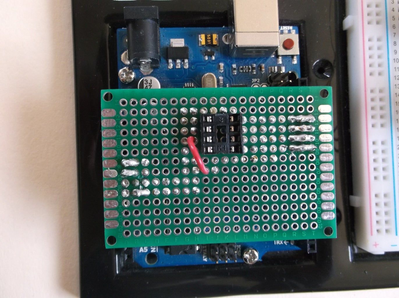
Before we start we should know how to hook up the attiny85 to the Arduino. The picture above shows the connection to the Arduino but the second picture shows the connections on the finished project.
The real picture is from the under side so it is not opposite of the drawing also I have not included the connection to the IC socket.
Step 3: Male Header Pins


-First we have to insert the 4 header pins into the female headers which are 13,12,11, and 10. Next you need to insert the power and ground pins to the Arduino (5v and ground that is)
- Then place your pref-board on top of the pins making sure the pins go through the wholes like in picture 3.
- Now keep you pins in the same place and solder the short side of the male headers like in picture 4.
Step 4: IC Socket

-Now you must insert the IC socket into the board. Align it with the 4 male headers like in the first pic.( try to put it in the center of the board.
-Once you are satisfied solder the IC onto the board.
Step 5: Connections


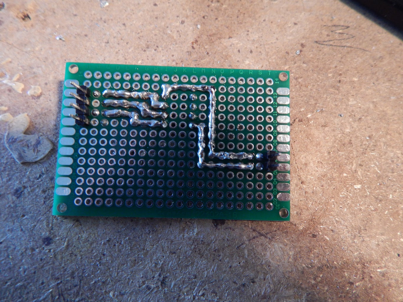
- Now you are going to to use track soldering to connect the pins to the socket
-First over lap the pins with solder at least on hole over like in picture 1. When you flip the board you see pieces of solder poking through the holes.
-Start with the for pins, solder the top pin to the second pin down on the left side of the socket,
solder the second to top pin to the third pin down on the left side of the socket, then
solder the third top pin to the bottom pin on the left side of the socket. (picture 2)
-Now for power and ground, solder the power header pin to the top left pin of the socket then solder the ground header to the bottom left pin of the socket. (picture 3)
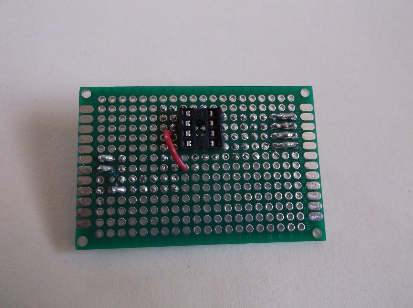
Step 6: Reset Pin

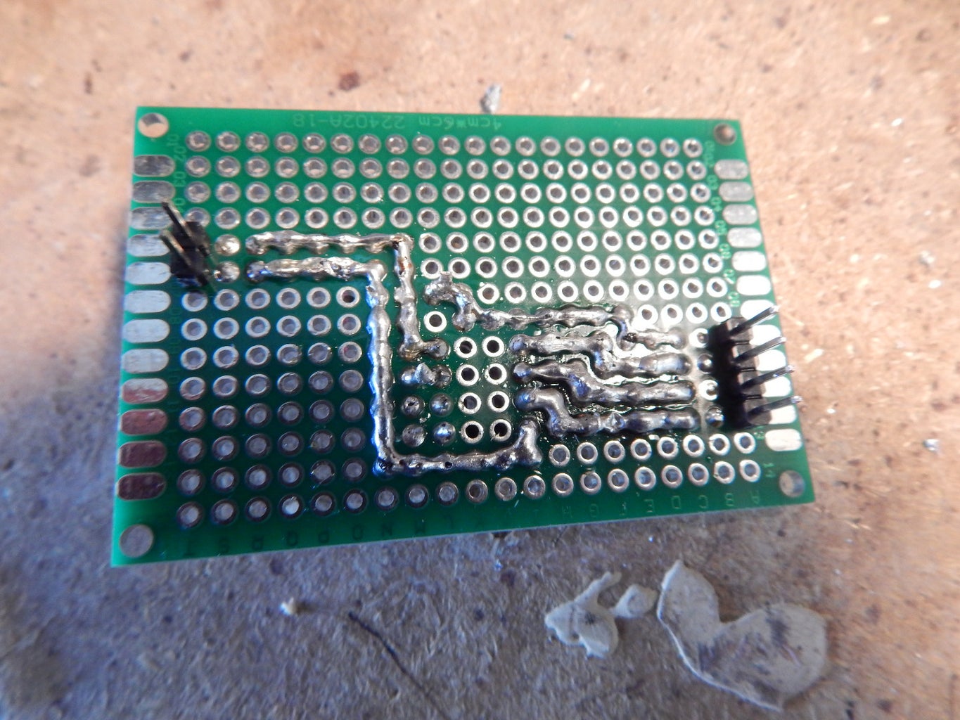

This part may be a little hard to explain but you are basically using wire to jump the connections to connect the reset pin. LOOK AT THE PICTURES!!!!!!
- First create a solder track from the bottom header pin (of the four header pins) that stops two holes below the right side of the socket.
-Now insert a small piece of wire that will connect the header pin to the top right pin of the socket (pic. 3)
- Finish soldering the wire to the top right pin of the socket.
Step 7: Finished

You are now done! Use this amazing shield to quickly program the attiny85. I hope this may be useful, feel free to leave suggestions, questions and any other comments you might want to add.
Good Luck!
