

Introduction: Auduino (Lo-fi Synth for Arduino)


Sketch created by Peter Knight, Tinker.it http://tinker.it.
For more information please visit the website.
I hope you are already familiarized with the arduino environment, if not get an arduino and check for more information at arduino.cc
Step 1: Materials
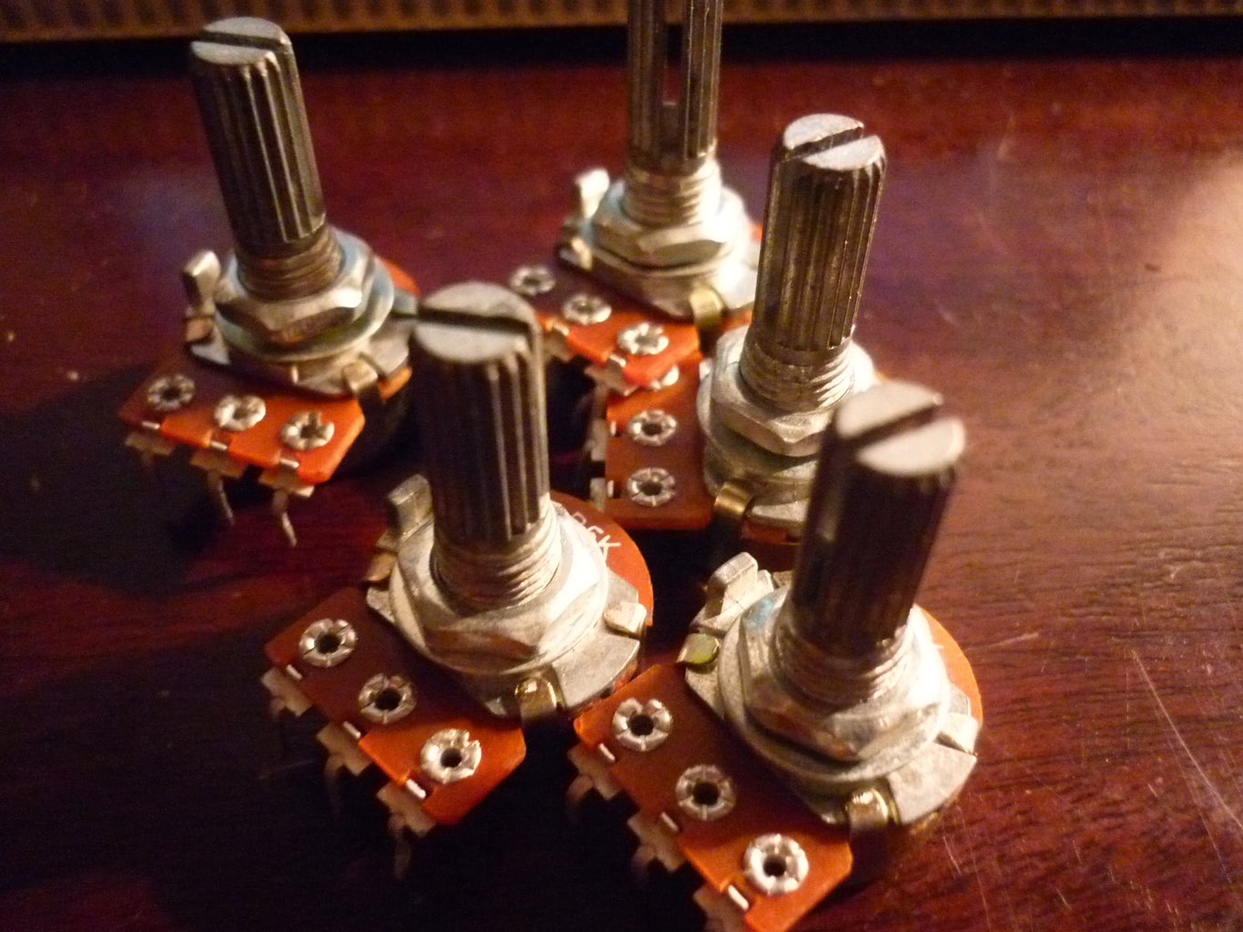


- X5 5K Potentiometer
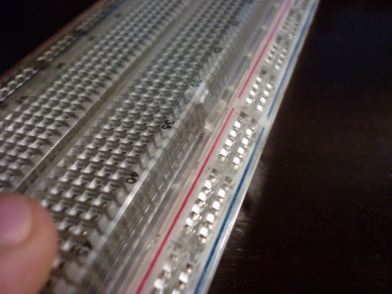
- A breadboard.
- An 8 Ohm speaker or a jack.
This you'll probably have laying around and will be needed:
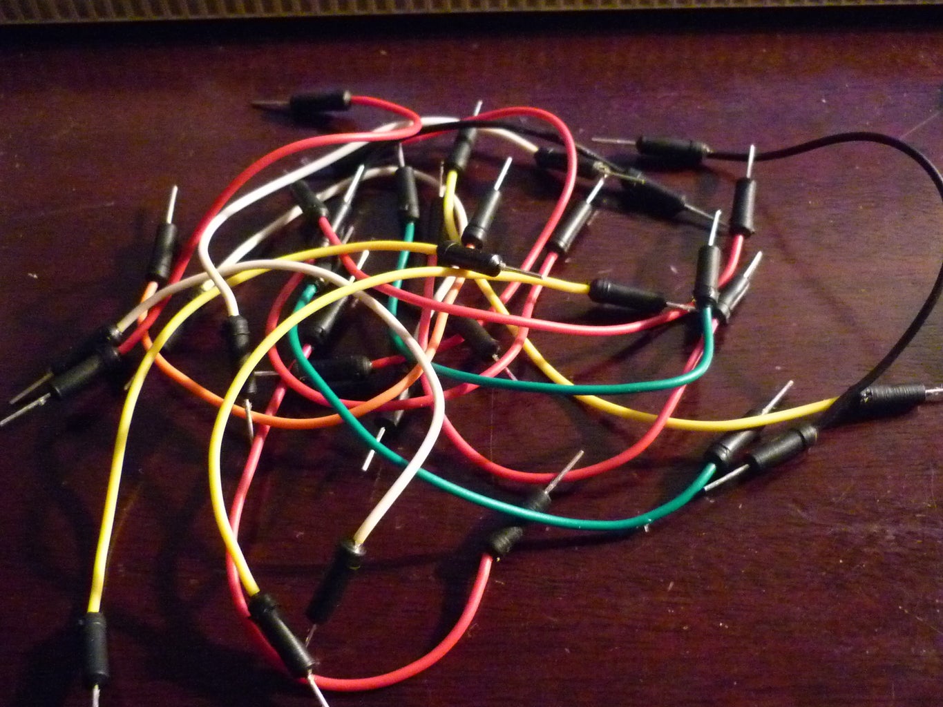
- Various jumpers
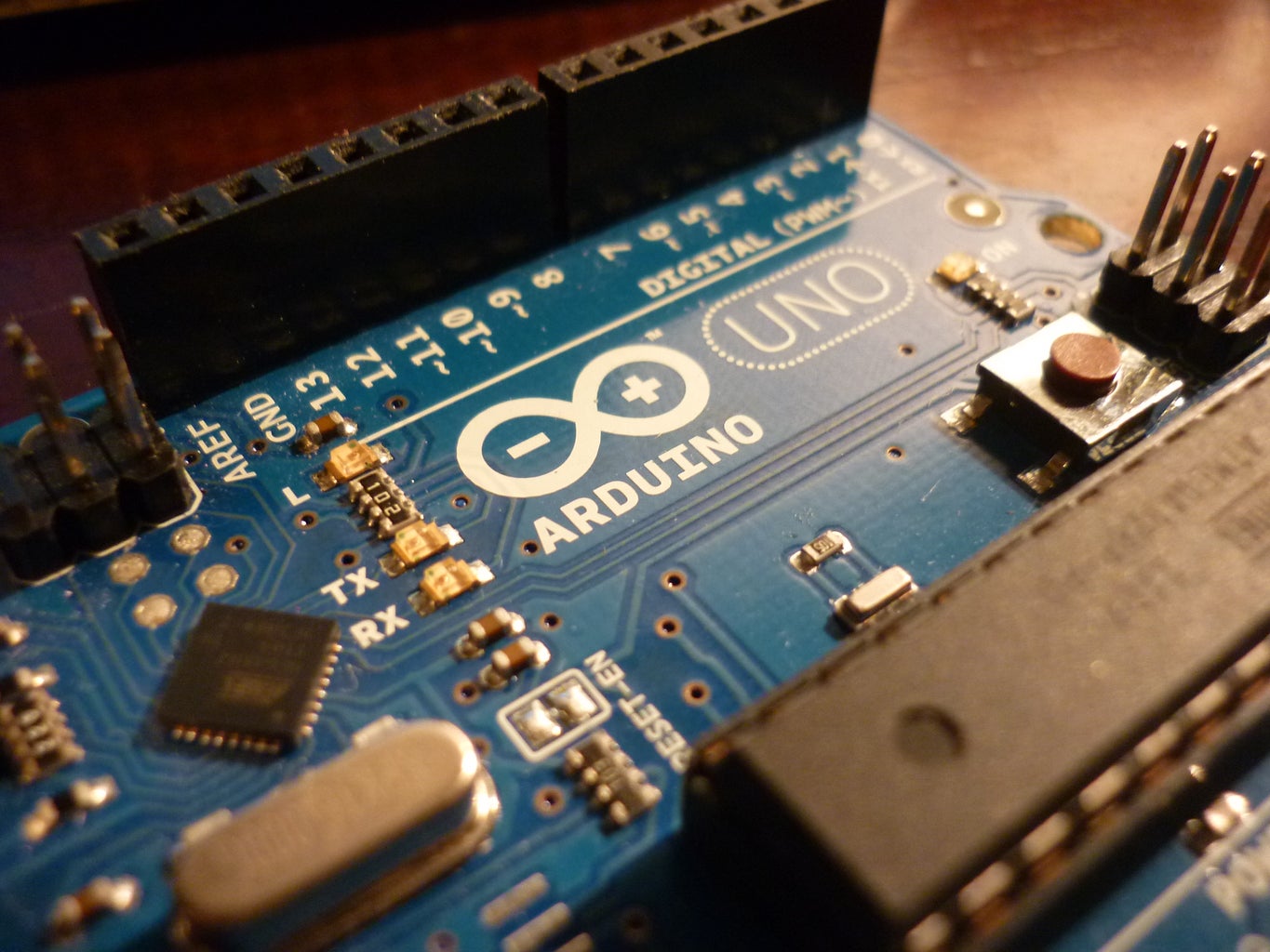
- X1 Arduino (I am using Arduino Uno R2)
Optional:
- X5 Knob (For the Pots)
Step 2: The Pots
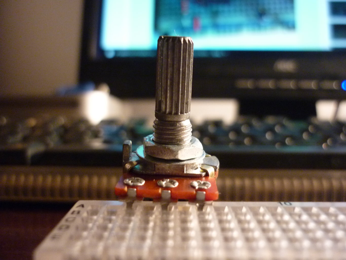

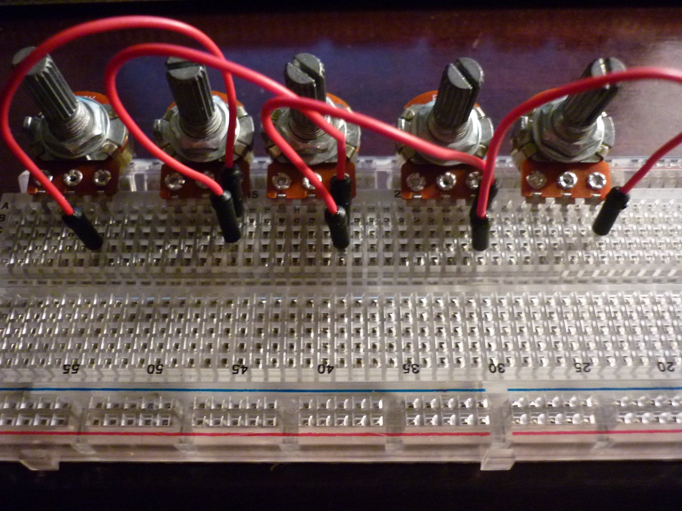


So the potentiometers go on the breadboard, I couldn't find the best stop for them because their back part wouldn't fit. But I managed to squeeze them in at the last row and I flexed the breadboard as shown in the picture.
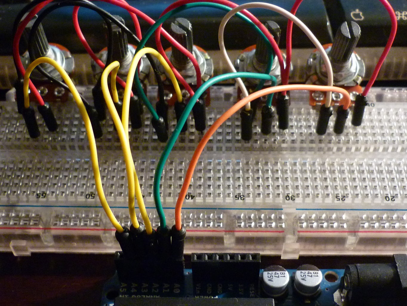
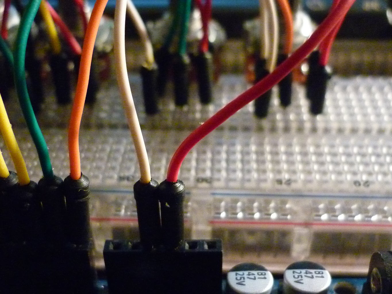
Basically all there positive leads are connected to 5V and all there negatives are going to ground. And the pots middle lead goes to an analog pin on the arduino.
Pot 1 goes to analog 4.
Pot 2 goes to analog 3.
Pot 3 goes to analog 2.
Pot 4 goes to analog 1.
Pot 5 goes to analog 0.
The pictures show how to connect the jumpers very clear.
Step 3: The Speaker
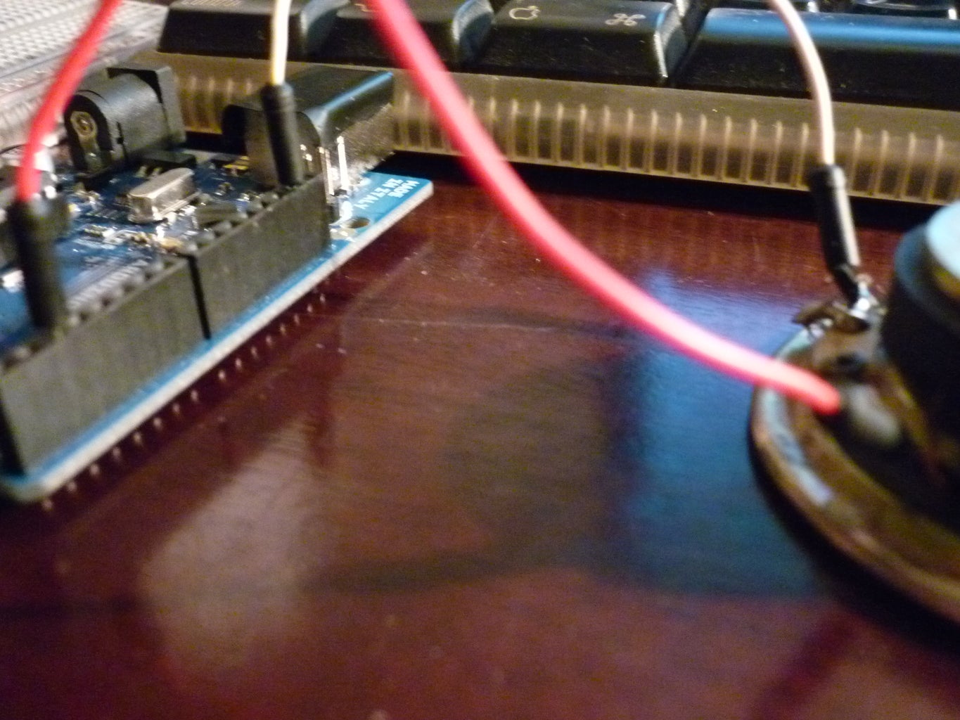
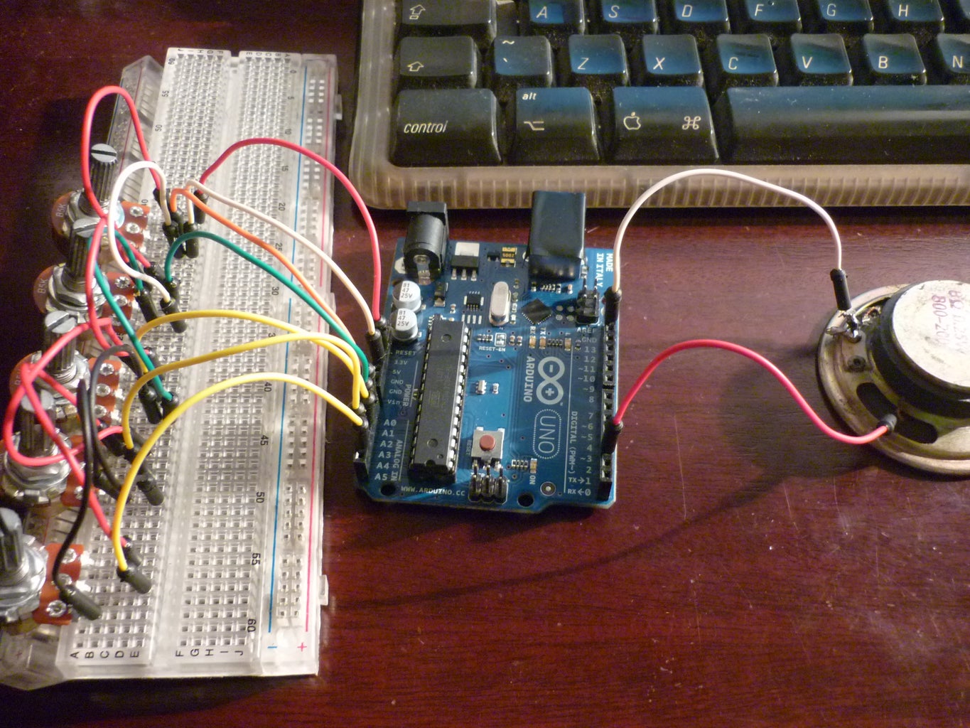

I used a speaker but you can use a jack and connect it to the same arduino pins.
Speaker must go connect to digital 3 on the arduino. And negative to ground...
Step 4: The Code
You can download the sketch here or you can just paste the code below on your arduino program and start to upload.
// Auduino, the Lo-Fi granular synthesiser
//
// by Peter Knight, Tinker.it http://tinker.it
//
// Help: http://code.google.com/p/tinkerit/wiki/Auduino
// More help: http://groups.google.com/group/auduino
//
// Analog in 0: Grain 1 pitch
// Analog in 1: Grain 2 decay
// Analog in 2: Grain 1 decay
// Analog in 3: Grain 2 pitch
// Analog in 4: Grain repetition frequency
//
// Digital 3: Audio out (Digital 11 on ATmega8)
//
// Changelog:
// 19 Nov 2008: Added support for ATmega8 boards
// 21 Mar 2009: Added support for ATmega328 boards
// 7 Apr 2009: Fixed interrupt vector for ATmega328 boards
// 8 Apr 2009: Added support for ATmega1280 boards (Arduino Mega)
#include <avr/io.h>
#include <avr/interrupt.h>
uint16_t syncPhaseAcc;
uint16_t syncPhaseInc;
uint16_t grainPhaseAcc;
uint16_t grainPhaseInc;
uint16_t grainAmp;
uint8_t grainDecay;
uint16_t grain2PhaseAcc;
uint16_t grain2PhaseInc;
uint16_t grain2Amp;
uint8_t grain2Decay;
// Map Analogue channels
#define SYNC_CONTROL (4)
#define GRAIN_FREQ_CONTROL (0)
#define GRAIN_DECAY_CONTROL (2)
#define GRAIN2_FREQ_CONTROL (3)
#define GRAIN2_DECAY_CONTROL (1)
// Changing these will also requires rewriting audioOn()
#if defined(__AVR_ATmega8__)
//
// On old ATmega8 boards.
// Output is on pin 11
//
#define LED_PIN 13
#define LED_PORT PORTB
#define LED_BIT 5
#define PWM_PIN 11
#define PWM_VALUE OCR2
#define PWM_INTERRUPT TIMER2_OVF_vect
#elif defined(__AVR_ATmega1280__)
//
// On the Arduino Mega
// Output is on pin 3
//
#define LED_PIN 13
#define LED_PORT PORTB
#define LED_BIT 7
#define PWM_PIN 3
#define PWM_VALUE OCR3C
#define PWM_INTERRUPT TIMER3_OVF_vect
#else
//
// For modern ATmega168 and ATmega328 boards
// Output is on pin 3
//
#define PWM_PIN 3
#define PWM_VALUE OCR2B
#define LED_PIN 13
#define LED_PORT PORTB
#define LED_BIT 5
#define PWM_INTERRUPT TIMER2_OVF_vect
#endif
// Smooth logarithmic mapping
//
uint16_t antilogTable[] = {
64830,64132,63441,62757,62081,61413,60751,60097,59449,58809,58176,57549,56929,56316,55709,55109,
54515,53928,53347,52773,52204,51642,51085,50535,49991,49452,48920,48393,47871,47356,46846,46341,
45842,45348,44859,44376,43898,43425,42958,42495,42037,41584,41136,40693,40255,39821,39392,38968,
38548,38133,37722,37316,36914,36516,36123,35734,35349,34968,34591,34219,33850,33486,33125,32768
};
uint16_t mapPhaseInc(uint16_t input) {
return (antilogTable[input & 0x3f]) >> (input >> 6);
}
// Stepped chromatic mapping
//
uint16_t midiTable[] = {
17,18,19,20,22,23,24,26,27,29,31,32,34,36,38,41,43,46,48,51,54,58,61,65,69,73,
77,82,86,92,97,103,109,115,122,129,137,145,154,163,173,183,194,206,218,231,
244,259,274,291,308,326,346,366,388,411,435,461,489,518,549,581,616,652,691,
732,776,822,871,923,978,1036,1097,1163,1232,1305,1383,1465,1552,1644,1742,
1845,1955,2071,2195,2325,2463,2610,2765,2930,3104,3288,3484,3691,3910,4143,
4389,4650,4927,5220,5530,5859,6207,6577,6968,7382,7821,8286,8779,9301,9854,
10440,11060,11718,12415,13153,13935,14764,15642,16572,17557,18601,19708,20879,
22121,23436,24830,26306
};
uint16_t mapMidi(uint16_t input) {
return (midiTable[(1023-input) >> 3]);
}
// Stepped Pentatonic mapping
//
uint16_t pentatonicTable[54] = {
0,19,22,26,29,32,38,43,51,58,65,77,86,103,115,129,154,173,206,231,259,308,346,
411,461,518,616,691,822,923,1036,1232,1383,1644,1845,2071,2463,2765,3288,
3691,4143,4927,5530,6577,7382,8286,9854,11060,13153,14764,16572,19708,22121,26306
};
uint16_t mapPentatonic(uint16_t input) {
uint8_t value = (1023-input) / (1024/53);
return (pentatonicTable[value]);
}
void audioOn() {
#if defined(__AVR_ATmega8__)
// ATmega8 has different registers
TCCR2 = _BV(WGM20) | _BV(COM21) | _BV(CS20);
TIMSK = _BV(TOIE2);
#elif defined(__AVR_ATmega1280__)
TCCR3A = _BV(COM3C1) | _BV(WGM30);
TCCR3B = _BV(CS30);
TIMSK3 = _BV(TOIE3);
#else
// Set up PWM to 31.25kHz, phase accurate
TCCR2A = _BV(COM2B1) | _BV(WGM20);
TCCR2B = _BV(CS20);
TIMSK2 = _BV(TOIE2);
#endif
}
void setup() {
pinMode(PWM_PIN,OUTPUT);
audioOn();
pinMode(LED_PIN,OUTPUT);
}
void loop() {
// The loop is pretty simple - it just updates the parameters for the oscillators.
//
// Avoid using any functions that make extensive use of interrupts, or turn interrupts off.
// They will cause clicks and poops in the audio.
// Smooth frequency mapping
//syncPhaseInc = mapPhaseInc(analogRead(SYNC_CONTROL)) / 4;
// Stepped mapping to MIDI notes: C, Db, D, Eb, E, F...
//syncPhaseInc = mapMidi(analogRead(SYNC_CONTROL));
// Stepped pentatonic mapping: D, E, G, A, B
syncPhaseInc = mapPentatonic(analogRead(SYNC_CONTROL));
grainPhaseInc = mapPhaseInc(analogRead(GRAIN_FREQ_CONTROL)) / 2;
grainDecay = analogRead(GRAIN_DECAY_CONTROL) / 8;
grain2PhaseInc = mapPhaseInc(analogRead(GRAIN2_FREQ_CONTROL)) / 2;
grain2Decay = analogRead(GRAIN2_DECAY_CONTROL) / 4;
}
SIGNAL(PWM_INTERRUPT)
{
uint8_t value;
uint16_t output;
syncPhaseAcc += syncPhaseInc;
if (syncPhaseAcc < syncPhaseInc) {
// Time to start the next grain
grainPhaseAcc = 0;
grainAmp = 0x7fff;
grain2PhaseAcc = 0;
grain2Amp = 0x7fff;
LED_PORT ^= 1 << LED_BIT; // Faster than using digitalWrite
}
// Increment the phase of the grain oscillators
grainPhaseAcc += grainPhaseInc;
grain2PhaseAcc += grain2PhaseInc;
// Convert phase into a triangle wave
value = (grainPhaseAcc >> 7) & 0xff;
if (grainPhaseAcc & 0x8000) value = ~value;
// Multiply by current grain amplitude to get sample
output = value * (grainAmp >> 8);
// Repeat for second grain
value = (grain2PhaseAcc >> 7) & 0xff;
if (grain2PhaseAcc & 0x8000) value = ~value;
output += value * (grain2Amp >> 8);
// Make the grain amplitudes decay by a factor every sample (exponential decay)
grainAmp -= (grainAmp >> 8) * grainDecay;
grain2Amp -= (grain2Amp >> 8) * grain2Decay;
// Scale output to the available range, clipping if necessary
output >>= 9;
if (output > 255) output = 255;
// Output to PWM (this is faster than using analogWrite)
PWM_VALUE = output;
}
Attachments

Step 5: Wrap Up


Some extras would be adding knobs. :)
Any progress or anything for the style, I will write down here.
Write in the comments what you did or if you have any questions.
Tobias
Plus a video I made so you can listen to the sounds of this synth:
Try to make a shield version! :)


