

Introduction: Automated Irrigation System Arduino Controller


In the summer of 2018 I had the opportunity to work with a senior at my college to finalize and finish up his senior engineering project. This project was an automated drip irrigation system at our campus garden. The system consists of a 550 gallon tank that is filled via rain water, a pump to circulate the tank's water, two solenoid valves, drip emitters, and various sensors such as 2 soil moisture sensors, a temperature sensor, a water sensor.
Although we are using this Arduino Controller for this irrigation system this design can be adapted for many other projects. Our Arduino is receiving information from our water level sensor, a temperature sensor, and the two soil moisture sensors to decide whether or not the tank valve should be opened for watering but adapting this design to work with more and/or different sensors should not be too difficult.
Our system works like this. The pump circulator, temperature sensor, and water level sensor are all mounted onto a wire cage frame. This frame is placed inside of the tank. The water level sensor is positioned about 6 inches above the bottom of the tank and when the water level drops below this sensor the controller turns on an LED signalling that the tank is low on water. The temperature sensor checks to make sure the temperature of the water is within the range defined by the user so that it doesn't damage the plants. Then the pump circulator moves the water around if it is too cold. After this set of checks our two soil moisture sensors send values to the Arduino about the soil's volumetric water content (VWC). These two values are averaged and if they lie below the (user defined) VWC lower limit the tank valve is opened and drip irrigation begins until the soil's VWC is satisfactory. These process runs every hour on the hour by using a real time clock.
The purpose of this project was to extend the growing season for our environmental center (EC). The EC provides local and real foods for campus dining via the Real Foods Challenge and it provides learning opportunities for students. However, campus irrigation only overlaps with the school year for around two months. By extending the growing season these educational opportunities can be more available while also increasing food production to provide an extra 600 lbs of produce.
Step 1: Gathering Necessary Supplies
To replicate this controller you will need:
- A soldering iron
- We used this one at 300 deg C:
- We used this one at 300 deg C:
- Solder wire
- We used this brand of 60-40 solder wire:
- We used this brand of 60-40 solder wire:
- An Arduino MEGA 2560 R3
- We used the Arduino MEGA because of the number of pins we had access to. It also has the added bonus of increased EEPROM storage and read/writes (used for saving parameters). You can use any manufacturer's mega, it should look something like this:
- We used the Arduino MEGA because of the number of pins we had access to. It also has the added bonus of increased EEPROM storage and read/writes (used for saving parameters). You can use any manufacturer's mega, it should look something like this:
- Solid core and/or stranded core wires (I find that they are better suited for different things)
- This type of solid core:
- This type of stranded core:
- This type of solid core:
- At least one Perma-Proto Full-sized Breadboard
- Some type of solderable board. It can be perf-board, strip board, perma-proto breadboards, etc.
- I used this type of board:
- When using these types of boards I ended up soldering the wires and resistors directly to the button headers and LEDs because there aren't any connections automatically being made (like on a breadboard). If I were to do it again I would use strip board so that this is an easier process. You could use fully stripped wire to make connections on this board but for this controller you really only need the boards for the buttons and LEDs. If I were to use strip board making the connections would've been vastly more simple.
- I used this type of board:
- 3x TIP120 Darlington transistors
- Any brand should do, here is an adafruit one but there are other sellers on amazon who offer more for a similar price:
- Any brand should do, here is an adafruit one but there are other sellers on amazon who offer more for a similar price:
- 5x buttons (button caps optional)
- Any button should do, ours came from our Arduino mega kit. This is the type of button used:
- Any button should do, ours came from our Arduino mega kit. This is the type of button used:
- 4x LEDs (we used orange, blue, red, and green)
- Any LEDs will do, here's a source that has 10 each of 6 different colors:
- Any LEDs will do, here's a source that has 10 each of 6 different colors:
- 1x UBEC DC/DC Down (Buck) Converter - 5V @ 3A output
- This is for taking the 12V battery power and converting it to 5V to safely provide power to the arduino and 5V components:
- This is for taking the 12V battery power and converting it to 5V to safely provide power to the arduino and 5V components:
- 1x LCD1602 Module
- The one I used was the one you'd get in an Arduino starter kit. I would've preferred not having pin headers presoldered because I had to solder wires and resistors to the pin headers so I recommend this one.
- The one I used was the one you'd get in an Arduino starter kit. I would've preferred not having pin headers presoldered because I had to solder wires and resistors to the pin headers so I recommend this one.
- 1x Adafruit Push-button Power Switch Breakout
- This is a pretty good power button. We also used a toggle switch before this but we found it slightly unreliable in the initial prototype.
- This is a pretty good power button. We also used a toggle switch before this but we found it slightly unreliable in the initial prototype.
- Resistors: This 1200 piece set should have 1k, 2k, 4.7k, and 220 ohm resistors:
https://www.amazon.com/1200-PCS-Resistor-Assortmen...- You need at least:
- 7x 1k ohm resistors
- 1x 2k ohm resistor
- 1x 4.7k ohm resistor
- 5x 220 ohm resistors
- You need at least:
- 3x 1N4007 Diode rectifiers
- 1x DS3231 Precision RTC Breakout
- We used the adafruit brand one:
- We used the adafruit brand one:
- 1x 12mm 3V Lithium Coin Cell Battery (CR1220)
- You can use any brand battery as long as its the right size
- You can use any brand battery as long as its the right size
- 4x 2-pin JST SM Plug + Receptacle Cable Set
- We used these for power (connecting to the battery), for the pump circulator, tank and drain valves, which all operate at 12V so these plugs definitely work at that voltage.
- We used these for power (connecting to the battery), for the pump circulator, tank and drain valves, which all operate at 12V so these plugs definitely work at that voltage.
- 4x 3-pin JST SM Plug + Receptacle Cable Set
- We used these for the two moisture sensors, the water sensor, and the temperature sensor
- We used these for the two moisture sensors, the water sensor, and the temperature sensor
- 1x VH400 soil moisture sensor
- 1x EC5 soil moisture sensor
- 2x 12V DC Brass Solenoid Normally Closed Valves
- Make sure the sizing is correct for your piping, these are simple to use because all they need to open is 12V.
- 1x Optomax Digital Liquid Level Sensor
- 1x DS18B20 Digital Temperature Sensor (the adafruit one comes with a 4.7k ohm resistor)
This is housing specific stuff, if you want to use the same case as we have and the same double sided PCB board
- 1x Junction box, IP65 rated
- This is the one we used. There is quite a bit of extra space which is useful with all the wiring.
- This is the one we used. There is quite a bit of extra space which is useful with all the wiring.
- M3 screws, 10 mm long. These are used for the LCD1602 module and for the adafruit power button. We fastened the module to the case's lid using these screws and matching nut fasteners.
- M1.6 Screws, 10 mm long, with matching nut fasteners. These were used for the double sided PCB board. They won't be necessary if you choose a different board that has differently sized holes
- You'll also need some drill bits, screwdrivers, a ruler for measurements, a rotary tool (dremel), a box cutter, masking tape, safety glasses, and an appropriate workspace.
Step 2: Overall Schematic

The controller circuit can look pretty complicated but it isn't very complicated once you get the hang of things. My partner was the one who put these resources together and as a person who wasn't familiar with Arduino at all just 3 months ago, I was able to put this controller together.
There are three files I've attached that I found very useful when used together.
- Schematic and Parts List (word document) -- this word document just has the schematic image along with a couple zoomed in photos that label everything. It clearly shows what parts need what resistor, what the sensors are, which lines are 5V or 12V or 3.3V. This document is useful for getting that information but if you want to be able to navigate around the schematic, zoom in and follow where each wire goes, the next two files are going to be what you need.
- Fritzing file (open using fritzing) -- this is the program my partner used to create the schematic diagram. You're going to be able to zoom in and see the schematic very clearly using this program. I find that it gets a bit buggy at times however, so I'd recommend using the png file of the schematic if this is all you want to do.You can also edit the schematic using the program. So, if you are using the basic design of this controller but are adding in your own features, you can just erase the things you don't need and add in whatever you want. Or if you are adapting this design to work with a different Arduino, like an UNO, you can still use this file to diagram it all out.
- Irrigation Controller image -- this is just the fritzing file exported as a png file. Since Fritzing can get buggy I'd recommend using this file for figuring out where each wire is heading. I just used the default Photos program in Windows 10 and it was easier than using fritzing.
These are the main resources I used and I would recommend using the "schematic and parts list" document and the irrigation controller image together when building this controller (and also this instructables tutorial). I'm going to be going into detail about how to construct this thing step by step though so stay tuned.

Step 3: Wiring Up the User Interface
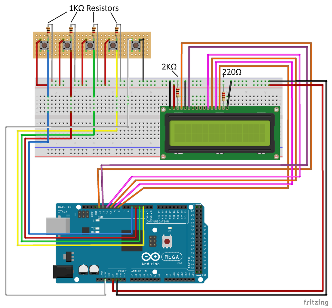


Wiring up the buttons and the LCD screen is the easiest part of the controller and will let you get started coding right away once you have them hooked up.
WARNING: If you are planning on building your controller exactly as mine, I suggest either using flexible wiring for this step or moving on to step 4 to do the transistor wiring beforehand. Doing the user interface stuff before the transistor wiring when you are trying to fit it all on a single perma-proto breadboard can be challenging. This is only because I squeezed the transistors in between the buttons though so if you are using an additional board or are not controlling 12V devices feel free to wire this up first.
You will need these components:
- Buttons (we used five of them)
- 1k ohm resistors (we used five of them)
- One 2k ohm resistor and one 220 ohm resistor for the LCD
- A LCD1602 Module
- Soldering tools, wire, some type of solderable board
Wiring on the buttons is simple. You just need to connect the top left pin to 5V, connect the top right pin to ground using a 1k ohm resistor somewhere in between, and connect the lower right pin to whatever Arduino pin you want to use. For the first four buttons they will be going to digital pins 5, 4, 3, and 2. The fifth button is our reset button and instead of going to a digital pin it goes straight to the reset pin on the Arduino. There is no coding required for the reset button.
Wiring the LCD up is also fairly simple.
- VSS is going to ground
- VDD is going to 5V
- V0 has a 2k ohm resistor going to ground
- RS is going to pin 13
- RW is going to ground
- E is going to pin 12
- D0 is blank
- D1 is blank
- D2 is blank
- D3 is blank
- D4 goes to 11
- D5 goes to 10
- D6 goes to 9
- D7 goes to 8
- A has a 220 ohm resistor going to 5V
- K is connected to ground
Once you are finished wiring you should be able to upload our Arduino code and be able to navigate around the user interface. Push the mode button to cycle between Standby mode, Parameter mode, Manual mode, and Sensor Read mode. In Parameter mode you'll be able to use the addition and subtraction buttons to adjust parameter values. This is an easy way to test and make sure the wiring is all correct.
The five buttons from left to right are:
1. Addition and Yes button
2. Subtraction and No button
3. Next button
4. Mode button
5. Reset button
I will be explaining how these buttons work in the code later one. In the further resources section of this tutorial there is also a manual that explains how to work the controller in better detail.
-------------------------------------------------------------------------------------------------------------------------------------------------------
Here are just some additional notes and things I would do differently:
Wiring up the buttons and screen the way I did was way more difficult than it needed to be. If you look at the pictures I took then you should be able to see that I soldered wires directly onto the buttons and LCD pin headers. The double sided PCB board I used doesn't work like a breadboard, there aren't any connections being made across the board so each hole is isolated essentially. If I had known about and used strip board instead then I could've used the boards similar to how breadboards are used and avoided soldering directly onto the button's pins and the LCD's pins.
I also recommend getting an LCD without the pin headers presoldered on. You don't really need pin headers if the LCD is going into a permanent project like this. You could desolder the pin headers from the LCD but it can be difficult and if you got your LCD from one of those Arduino starter kits I would avoid doing this. Another way would be to use strip board but again, if this is going into a permanent project I would just order a screen without pin headers.
Finally, I think stranded wire may have been better to use since it is more flexible and I would've been able to get a better angle the breadboard later on. I only had solid core wire when I started and it was somewhat easy to use (unless I needed very short wires) but the buttons and screen are very rigid and not mobile at all. I ended up melting the wires' insulation somewhat often later on and breaking resistors.
Step 4: Transistor Wiring


This is probably the most challenging part of building this controller but this is mostly due to my insistence on only using one perma-proto breadboard. I'm quite happy with how this part turned out. There was just enough space in between the button wiring to squeeze the transistors and their wiring in. If I were able to redo the entire controller with all the parts on hand, I'd probably do this step first. Although it was a challenge squeezing this stuff in, it is not all that complicated. You also won't need to do this wiring unless you have 12V devices you want to control.
First look over the two fritzing images I've attached. The first shows only the wiring for the first transistor, which is connected to the pump circulator. The next image shows complete wiring for the tank and drain valve and the water level sensor, in addition to the pump circulator. I'm going to focus on the first image for now.
Transistors are basically gate keepers for the 12V line. There is an input pin, an output pin, and a 'control' pin. 12V from our battery is constantly going into the transistor and a diode prevents any voltage from the arduino from going the opposite way. When the 5V pin isn't activated the 12V is not allowed to pass through to the 12V pump circulator. When we do activate the 5V pin (via the arduino and its code) this gate is opened up and the 12V from the battery can reach the 12V pump circulator and turn it on.
The blue, red, green, and yellow lines represent the rows reserved for the button wiring. If you look at the previous step you'll see this. There are five rows between each button if you followed the instructions exactly which is enough to center each transistor. From left to right each transistor is used to control the pump circulator, the tank valve, and the drain valve. The orange LED is used for the water sensor (whose full wiring is shown in the second fritzing image), the blue tells you if the pump circulator is on, the red tells you when the tank valve is open, and the green tells you when the drain valve is open. So the first transistor gets wired with the blue LED, the second gets wired with the red, and the third gets wired with the green.
For now, focus on wiring up the first transistor.
- Solder the transistor to the board, make sure the black part is facing towards you. This step can be difficult since the transistor won't sit still without extra help. Electrical tape can be helpful but if you are using the soldering iron for too long it will begin to melt. The transistor will get very hot, avoid using your hands to hold it in place. My recommendation is to use a 'helping hands' device like this: https://www.amazon.com/ProsKit-900-015-Helping-Han... which will help out a ton. Tweezers can help too but it will still be difficult without another person holding the transistor still for you.
- Next, you should connect the right leg to ground. In my controller I am using the perma-proto breadboard to connect everything to ground. There is only one ground rail and it is on top of the board next to the 5V rail. If you look at the fourth image, I used the extra space in the back to connect the right leg to ground. Those are the short black wires.
- The middle leg is where you hook your 12V devices to. In our controller we are using plugs so the controller can easily be disconnected when it needs to. This is what the 2x8 strip board off to the left represents. Our pump circulator, tank valve, and drain valve only need 12V to activate so the wiring consists of power and ground. With our sensors there will be three wires, power, ground, and data. Connect the 12V device's ground to the middle leg. A diode then needs to be placed with the white stripe facing away from the transistor and the device's ground. After the diode you connect the device's power and finally you connect the everything to the 12V rail. If you are using plugs, keep track of which wire on the plug is ground and power and be consistent with all the other plugs.
- The left leg is where you connect the transistor to the Arduino. It goes left leg, 1kΩ resistor, wire connecting to the device's associated LED (which will be blue for this first transistor), and then wire connecting to an Arduino pin (40). The great thing about doing it this way is that you don't need a separate pin on the arduino for any of the LED signifiers. The single arduino pin can turn on the LED and activate the 12V device at the same time this way.
Now onto the second image,
- The water level sensor is located off to the far right. There will be a power, ground, and data line for the sensor so make sure you figure out which is which for the sensor you are using. The water level sensor's data is connected to pin 27, the LED associated with it is connected to pin 26. If you are using a 3-pin plug it'll be just like using 2-pin plugs, just keep track of which wire is power, ground, and data and make sure the order is consistent for all 3-pin plugs so its easier to keep track of.
- The wiring for the remaining two transistors is identical to the first. I diagrammed it out so that it is clear that this design is able to be expanded upon or modified.
Next we will cover where this 12V line comes from and how we are powering everything.
Step 5: Powering the Controller


This part is fairly simple. Look at the fritzing image first.
From the 12V battery we are using I've attached plugs coming from the battery and from the Arduino. That is the piece of strip board I threw in there. The battery's ground gets connected to the GND on the adafruit push-button power switch and its power gets connected to IN.
Both sides of the push-button power switch look identical so feel free to use whatever side you want.
Then you should connect the OUT pin on the power button's board to the designated 12V rail. Connect GND from the power button to the ground rail now. Finally the wire the UBEC's ground wire to the ground rail and power wire to the 12V rail. These will be the UBEC wires that don't end in a pin header. All that remains is to connect the other end of the UBEC to VIN and GND on the Arduino. This supplies the Arduino with power and now the 5V rail and 3.3V rail will be powered as well.
The flow of power works like this
Battery --> Power Button --> 12V rail --> UBEC --> Arduino --> 5V and 3.3V rails
Step 6: The Arduino Code
You will need a couple extra libraries to run this code:
Arduino-Temperature-Control-Library-master: https://github.com/milesburton/Arduino-Temperature...
OneWire: https://www.pjrc.com/teensy/td_libs_OneWire.html
RTClib_master: https://github.com/adafruit/RTClib
The Arduino Temperature Control Library and the OneWire library are necessary for us to use the DS18B20 temperature sensor. The temperature control library allows us to get the temperature and the OneWire allows us to wire the temperature sensor using only one wire (if you look at the schematic you'll see the temperature sensor is wired with its power and ground both connect to the ground rail. The data pin is both receiving power and communicating with the arduino).
RTClib is the library for the real time clock we are using, the DS3231.
You probably won't need the temperature control library or the one wire library if you aren't going to be using a temperature sensor but you should have them when you compile and put the code onto your controller. I'll be explaining everything further on though so feel free to build off the basic parts of the code.
Attachments
Step 7: Libraries, Global Variables, & Setup Code
So for the libraries we are using:
- LiquidCrystal -- For the LCD1602 module
- EEPROM -- For saving the user's parameters
- Wire -- For using the scl and sda pins on the real time clock
- RTClib -- For using the DS3231 real time clock module
- OneWire -- Needed for one wire use of our DS18B20 temperature sensor
- DallasTemperature -- Needed for getting temperature values
After we include this libraries then we set up the OneWire device (temperature sensor) and define the many global variables.
The variables that will not change consist of what pins we are using. It's pretty straightforward. The variables that will change are the parameters, button variables, and program variables.
Parameters are simple integers and there is a back up of them just to make sure users don't accidentally change something they didn't mean to.
- Button variables basically just track the state of a button which is useful every time we need to use the buttons for something.
- Program variables track what state of the program the user is currently in. modeState is for switching modes, parameterState is for the multiple screens we have in parameter mode, sensorState is the same thing as parameterState except for the sensor read mode, etc.
Next is the setup function.
- To begin with we read the last used parameters from EEPROM. EEPROM is like a tiny hard drive on the arduino that we save variables to. These values are preserved even if the Arduino is turned off. We also assign back up variables at this point.
- Next we set the pinMode for all our pins. Buttons and sensors are inputs to the arduino and the LED, pump, and valves are all outputs.
- The beginning code is important, I made a mistake of not including one of them and got so confused when the temperature sensor didn't work. lcd.begin just allows the LCD to work properly. sensors.begin does the same thing but with the temperature sensor. Serial.begin starts the serial monitor.
- The first if statement with rtc.begin actually starts the real time clock while also providing a message if it cannot start. The second if statement sets the time if the clock was reset by removing the battery.
That is all for set up! Next is the overall structure of the program.
Step 8: Program Explanation
The overall structure of the program is not that complicated. To begin with I'll introduce the many state variables we use. There is modeState, parameterState, sensorState, and autoState. There four variables help us move through the many parts of the program.
At the start of loop() the arduino reads the state of the mode button which is either HIGH (being pushed) or LOW (not being pushed). If the button was pushed we add one to modeState. We run this code only if modeState is less than 4 and it isn't equal to 5. So what are these mode states then?
- Standby Mode (modeState == 0): this mode's only job is to check the time and run auto mode every hour on the hour. We do this via checking the current time and seeing if the seconds and minutes are equal to zero. If they are then it means the time looks something like this --> XX:00:00. When this does happen modeState is set equal to 5 which is Auto Mode.
- Parameter Mode (modeState == 1): this mode allows the user to change and set parameters. This is also where parameterState is used. The structure of this mode is identical to the overall structure of the program.
- Start Screen (parameterState == 0): this screen just tells the user to push the next button to continue through parameter mode. The next button code is identical to the mode button code.
- Setting the Upper VWC Parameter (parameterState == 1): this screen displays the UpperVWC variable and allows the user to change it using the add and subtract buttons.
- Setting the Lower VWC Parameter (parameterState == 2): same as previous screen but with the LowerVWC now
- Setting the Temperature Upper Limit Parameter (parameterState == 3): same as previous screen but with tempUpperLimit
- Setting the Temperature Lower Limit Parameter (parameterState == 4): same as previous screen but with tempLowerLimit
- Displaying the changed parameters (parameterState == 5): just shows all four parameters so the user can double check things
- Asking to save parameters screen (parameterState == 6): asks the user if they would like to save these new parameters. If yes it moves on, if no it uses the back up variables to revert any changes made.
- Saving to EEPROM (parameterState == 7): this saves the new parameters to EEPROM so they can be used next time the controller gets turned on and also changes the back up variables to match the new parameters.
- Looping back to the start screen (parameterState == 8): this just goes back to the start screen. I could've put this bit of code in the previous parameterState honestly.
- Manual Mode (modeState == 2): this mode allows the user to manual control the pump circulator, tank valve, and drain valve. The color of our buttons and the color of our LEDs correspond with each other. This is also where those button states variables and the manualControl variables come in handy. Before we had to hold down the button if we wanted the pump to stay on or the valves to remain open. Now we can simply push the button once to turn on and push again to turn off. We also have coded the tank valve button to automatically open the drain valve afterwards.
- Sensor Read Mode (modeState == 3): this mode lets you read all the sensors and it also uses the sensorState variable
- Start Screen (sensorState == 0): tells the user to push next to continue through sensor read mode
- Water Level Sensor Screen (sensorState == 1): this screen reads the water level sensor pin. If it reads HIGH that means there is no liquid touching the sensor so it turns on the water level LED to indicate that the tank needs to be refilled. If it reads LOW then liquid is touching the sensor and the light remains off showing that the tank does not need to be refilled.
- Temperature Sensor Screen (sensorState == 1): this screen reads the temperature and displays it in degrees Fahrenheit.
- Moisture Levels Screen: this screen shows the VWC readouts from our two sensors. S1 is the VH400 and S2 is the EC5.
- Looping back to the start screen (sensorState == 4): this makes sure the water level LED has turned off and returns the user to the start screen of Sensor Read Mode
- Returning to Standby Mode (modeState == 4): The water level LED is once again turned off (there was a bug where if you switched modes while on the water level sensor screen the LED would remain on) and all the program variables are reset. This is so that when you switch modes again you end up on the mode's start screen instead of finding yourself on one of the many sub-screens.
- Auto Mode (modeState == 5): this is the meat of the program where we run many checks before deciding to water the garden. autoState is used here. There also aren't any screen changes (you could add some but the arduino runs through these checks so quickly you'd have to slow the program down to even see a screen change).
- Checking the water level (autoState == 0): just reads whether the water level sensor is HIGH (no water) or LOW (there is water) like in sensor read mode. If there is water it moves onto the next step. If there is no water it turns on the refill water LED and goes back to standby mode.
- Checking the water temperature (autoState == 1): checks to see if the current temperature is within the established range of tempLowerLimit to tempUpperLimit. If it is then it moves onto the next step. If it is too cold it turns on the pump circulator for 5 seconds and then checks again in an hour (back to standby mode). If it is too hot it just checks again in an hour (back to standby mode).
- Checking the soil moisture sensors (autoState == 2): this step reads the analog values from the VH400 and the EC5, converts them to values we can use, and averages both of them. If the averageSoilSensorVal is below VWC_Lower the garden should be watered. If it is between the lower limit and upper limit the moisture is in the green zone and the garden should not be watered (back to standby mode). If it is above the upper limit like if it rains then the garden should not be watered (back to standby mode).
- Closing the valve step (autoState == 3): this step checks VWC of the soil again by reading the soil moisture sensors. Once it passes the upper limit the tank valve is closed and it moves onto the last step.
- Opening the drain valve step (autoState == 4): this step opens the drain valve for 1 minute (60000 milliseconds) and then closes it before going back to standby mode.
Step 9: Completion and Testing
Now that the controller is complete we can test it in a variety of ways. The easiest method is to use manual mode to turn on whatever devices you are using. The blue, red, and green LEDs should light up when you press the same colored buttons. Remember, if you are controller 5V devices you only need to connect the power line to the Arduino instead of using transistors. If you are using 12V devices make sure the power wiring resembles ours.
Sensor read mode is another good method of testing. If you are using the same temperature sensor, water sensor, or soil moisture sensors you can easily see if they are working correctly.
If you can set up a similar irrigation system that'd be fantastic for testing. We found that watering the plants is a slow process (we are using drip emitters and are relying on gravity instead of a pump). Our emitter has four lines and we found that if we closed off two of them the watering process got sped up substantially. The soil also stayed moist for around 3-4 days after watering completed (but we didn't test on the garden plants).
There is an issue where when we use the controller with a 12V battery the LCD screen does not receive enough power. One work around is to take power straight off the UBEC before it goes into the VIN pin on the Arduino but this does not make the LCD work how it would normally work off USB power. Let me know if you find a solution for this!
I have also included the irrigation controller manual which explains all the user interface buttons and the various modes. There is also a basic maintenance guide, a diagnostics and troubleshooting section, and some additional code documentation and explanation. If you are having trouble check out the manual.
Step 10: Things We Learned
- We used this type of converter before switching to the UBEC: https://www.adafruit.com/product/2190
- The issue with it was that our battery was 14V, not 12V so we burned a couple of them back to back trying to figure out why (its range was 3V-12V). The UBEC has a range of 6V-16V.
I learned a ton about using Arduino by working on this project. I experimented with turning LEDs on and other basic starter projects beforehand but that was it. I didn't know anything about how to use a temperature sensor, how to control a 12V valve or pump, or how to add a menu to an Arduino program.
- Double check everything and test often!
- I had to rewrite the code twice because I wrote large chunks of code without testing it in pieces. I couldn't find out where the error was so I added everything back in piece by piece.
- I also checked my wiring upwards of 8 times because the temperature sensor wasn't working for some reason. It turned out I forgot to include "sensors.begin();" in the setup loop.
Watering in our system is slow, our tank is elevated 3ft above ground level. In order to speed this up either the tank must be elevated further or a pump must be used. A pump would rapidly drain the battery out there. The pump circulator we are using is only on for 5 seconds at a time.


