

Introduction: Automated Solar Powered Horizontal Blind Controller


Update: Check out my updated version of blinds: Smart Blinds
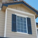
I started this project because we have some horizontal blinds located in a high window over the main door to our house. This window faces south, and here in Colorado, that means LOTS of sunshine. It'd be nice to have that sunlight shine into the house during the winter, and be able to shade the window when the weather gets warmer in summer.
Another consideration was the blinds needed to shut at night to provide more privacy in the upper level.
I had seen some automated blinds, but none that did exactly what I wanted, and I hadn't found any that were completely hidden or required running wires down the wall. There's no outlet close to this window, and wires on the wall were never even considered to be an acceptable solution. Since access to this window requires a ladder, the battery-powered system has to last a long time.
After some research I settled on a servo motor, and after reading some of the instructables on this site (Deba168's Weather Station was a good one), I came up with the design in this instructable.
Requirements:
- Fully autonomous - light-sensitive, temperature-controlled (Open when it's light out, Close when it's dark, Close when it gets too hot)
- Hidden from view - no wires (too many designs I saw relied on 110V power, or a box mounted next to the blinds)
- Solar powered (Hey, it reduces my work and it's green, to boot!)
- Cheap (everything cost about $55 US - and I've since found several items cheaper, which is great since I need to build two more of these)
Step 1: Parts List
Unfortunately, I didn't think I was going to create instructions at first, so I don't have a nice picture of all the components. Here's what you need (Yes, I order a lot from Amazon - you can probably find it cheaper. And a lot from Sparkfun, they're local and I like them):
- Arduino pro mini (5V) (Sparkfun)
- Solar panel (5V) (Amazon)
- Diode (for Solar panel)
- Zener Diode (in case you make the same mistake I made)
- Lithium Ion Battery (3.7V) (Amazon)
- AA Battery holder (18650 is all I could find) (Sparkfun) - I just realized they also sell individual clips that I could maybe have used, I would have had to mount them somewhere though.
- Lithium Ion charging module (Amazon)
- DC-DC Boost Converter (5V) (Amazon)
- Temperature sensor (I used the TMP36 that came with my Arduino Uno starter kit - rev 2 will use a LM35DZ)
- Servo motor (I used a Hitec HS-325HB that I found at a local hobby store) (Here's an equivalent) I had to take a guess at what kind of torque was necessary. I couldn't find a reasonably-priced torque wrench to make a measurement.
- Servo motor coupling (Sparkfun)
- 0.1 uF capacitor
- 10K-ohm resistor
- Light Dependent Resistor
- Circuit board/Solder breadboard
- Heat-shrink wrap
Useful items to have:
- Drill
- Soldering Iron
- Solder
- Wire
- Wire clippers
- Wire stripper
- Multimeter
- Dremel or similar small cutting tool
Step 2: Prototype and Measure First!


The first thing I did was (after reading many good solar instructables on this site!) was test out my 5V DC-DC converter and the solar panel.
I first hooked up just a standard 3.0V battery setup (2 AAs) to verify I was getting 5V from my booster. Check.
I also verified the voltage coming from my Solar Panel (not using sunlight - mistake #1). I was using an Ott light in the basement, where my workshop is. See the "Mistakes" section for more info.
I also measured the current draw when the motor was running vs. not running. This led me to use the LowPower library for Arduino. [link] It also gave me the idea to "detach" the servo after completing the necessary move.
Deba's Solar Powered Weather Station instructable has very good instructions for measuring current draw, complete with pictures and wiring, if you don't know how. But your multimeter should have come with instructions to do this too.
Prior to wiring ANYTHING up, I prototyped the software with the temperature sensor, Light Dependent Resistor (LDR), and servo motor setup in a breadboard. Simply use your hand to cover and uncover the LDR to simulate changes between light and dark. I used a hair dryer to simulate summer conditions and getting above the temperature limit. If possible, use the serial monitor to examine what your outputs are at the times of day you want the blinds to open and/or close. That's how I came up with the numbers in the code.
Step 3: Program the Pro Mini
Here's the code in a git repository.
If you don't zap your 5V DC-DC booster, then change the line "const int AREF_Voltage = 3.5" to 5.0.
A better practice would be to substitute 1024.0 with something like ANALOG_MAX - magic numbers are a bad practice.
You'll also need the TMP36 Class. The class was overkill. I was experimenting with creating classes and it seemed like an easy one to start. Plus, it'll be easily reusable for other projects. It's so simple you could take the conversion and just put it inline in the other code.
And the LowPower library from rocketscream.
Step 4: An Attempt at the Circuit

Ignore the (misspelled!) Solar Panel and Booster circuits on the left - Fritzing doesn't appear to have what I wanted, and I haven't spent the time to figure out how to add it.
Step 5: Assembly


This where I really failed the instruction planning. I don't have a good pic of my circuit layout except for this picture.
Panel to Charger:
- V+ from the solar panel goes to the charger V+ (I added an unnecessary diode between Panel+ and charger module +, because I didn't realize it had one there already)
- V- from the solar panel to the charger V-
Charger to Battery:
- Bat+ from charger to Battery Positive
- Bat- from charger to Battery/Circuit Ground
Battery to Booster:
- Battery Positive to Booster In+
- Battery Ground to Booster In-
- This step should really add the Zener diode to clip the voltage at 5V (a 5.1V would probably be fine, since the booster has a max input of 5.5V - I've ordered a 4.9V for my next iteration) But check your specs!
I made the mistake of using a 6V solar panel on my first design, which when it hit full sun seems to have fried my booster, as it now outputs exactly 0.2V less than the input Voltage, whatever that is (either 3.7V from the battery, or almost 6V when the panel is in the sun). Luckily, the 5V Arduino Pro mini runs on the 3.5V, but it did require a quick re-write of the code to account for the lower reference voltage.
Booster to Circuit:
- 5V out (my booster wasn't labeled, I had to figure out which pin on the underside this was) to a 5V rail. You'll create this for the rest of your circuit.
- Ground (measure to determine which pin) to common Ground (used for all the other components). You'll create this as well.
Circuit:
- 5V+ to the temperature sensor V+
- 5V+ to Arduino Pro Mini RAW
- 5V+ to the Servo Motor Red (+)
- 5V+ to the LDR V+
- Ground to temperature sensor Gnd
- Ground to Pro Mini Gnd
- Ground to Servo Motor Black (Gnd)
- Ground to 10K-Ohm resistor that is connect to the LDR opposite of the 5V+
- A0 to the connection between the LDR and the 10K-Ohm resistor (Voltage divider for light measurements)
- A1 to the temperature sensor signal pin
- Pin 9 to the Servo signal line.
Step 6: Installation


Now that the circuit is built, it's time to put it into the blind headrail.
Don't make the mistake I made - measure your circuit board and cut it down FIRST! I just barely was able to fit the circuit into the blinds, after trimming the circuit board down on two sides.
Remove the pull-cord for the blind angle adjustment. The screw drive that it is attached to will provide too much resistance for the servo motor to drive the blinds.
I taped the solar panel to the upper left corner of the window, since the blind controller is on the left side.
The battery fits to the left of the circuit board and underneath the servo motor. With no room to spare.
Step 7: Mistakes I Made!
Here's where you get to laugh at me.
1. I bought a 6V solar panel after reading about battery charging. I should have bought a 5V for two reasons:
a. It would be plenty of charge for a 3.7V battery
b. I would not have zapped my 5V DC-DC boost converter
This is important to note, because it forced me to re-write the code using a voltage reference instead of the raw analog values I had measured. So now it's more generic, more portable, but it wasn't my original 5V design.
2. I soldered the battery holder and solar panel to the circuit instead of using some kind of connector clips. So now I can't turn the circuit off if it's sunny out - which it mostly is. This makes it a little fun to install it
3. My dead band wasn't big enough to handle the slight amount of light reflected by the blinds when they're closed.
This actually created a hilarious couple of days where my children stated the blinds had oscillated back and forth before settling on the "open" position. Knowing that the code doesn't allow that, I was skeptical, until I was able to sit and watch them before leaving for work. Sure enough, the blinds opened, paused, then closed, paused, and then opened again. That's when I realized I was getting some light reflected back into the sensor. So there's about a 30- to 60-second window of time where the light is *just* bright enough to open the blinds when they're closed, but just dark enough to close them when they're opened. You could fix this with "don't change if the last change was less than 5 minutes ago" logic or by increasing the dead band.
4. Related to item #1.... The servo doesn't have the full capability it would have at 5V. As a result on the first day of operation, it worked fine. But when the blinds closed that night, they fell a little more closed than I expected (almost completely vertical). That extra resistance to get them past full vertical into a horizontal position proved too much for the underpowered servo. I thus had to stop the blinds at 170 degrees for closed instead of 180.
Step 8: Improvements Coming in Rev 2
- Better pictures - I found so much help on several DIY websites that I feel I owe it to give back. Thank you to all of those that have created quality instructions.
- More pictures.
- More details on the steps
- Correctly-sized Solar Panel (5V)
- Battery and Solar Panel quick-connectors (Molex or JST, haven't decided yet - whatever is cheap)
- Better dead band or position-change logic.
- Better circuit layout. I really lucked out when I did this. I made a few measurements then started soldering. I could just barely fit the finished circuit into the blind headrail.
One thing I'd like to do is make it somewhat modifiable without removing it and reprogramming it. I just haven't figured that out yet. Bluetooth? Wifi? USB Connector? If you have thoughts, feel free to share them.
Thanks for reading - I hope you have success with your project.


