

Introduction: Awesome LED Level Meter


This WAS going to be my entry to the 'Get the LED Out contest', but I was too slow.
I was bored one day. I wanted to build something cool. A quick bit of brainstorming and nothing came up. Digging through my junk boxes, I found a old level meter kit. I went over my mate's place later that day and we were having a killfest in Halo 3. He had seen this Level kit in use before, and wanted it rebuilt into a full-blown system to complement his surround system.
Here I'll guide yo on how to make your own.
Step 1: Parts


For this Project you will need:
Scrap wood
LED level meter kit (available here)
LED's of your choice.
power supply
Diodes (if using AC output supply)
Cable
Potentiometer
10 X BC558 or similar transistors.
Step 2: Tools


You will need the following tools:
Drill
Jigsaw
Multimeter
Spray Paint (optional)
Soldering Station
Solder
Wire Cutters
Step 3: Power Supply


The kit I used Needed a supply at around 9 - 13 V DC, at up to 250 mA. I had a 12V AC 280mA Plugpack (also called wall-warts) sitting around. But the circuit called for DC. What to do?
The solution was for me to make a simple diode bridge (bridge rectifier). It uses just 4 small power diodes.
I layed them out, soldered them together, added a supply and viola! 15V unloaded. Perfect!
Step 4: Transistors!!!


Now onto the kit. It originally had 3mm LED's but these had to be removed. After that, I examined the circuit. The LED's originally used a common positive and the chip switched the outputs low to light the LED.
This meant I needed a PNP transistor.
Enter the simple but effective BC558. Actually anything will do here. Everyone should have plenty of these in their parts drawers. If not, well, you'll need to go get some. 10, in fact.
After finding them, you'll need to cut their leads into a special shape. Not 100% necessary, but makes life easier.
See pictures for more info.
Bend the collectors to 90° behind them. Slot them into their respective holes and solder them in.
Step 5: Wood


I used wood as stands for the display. You can use other stuff, but I had a scrap shelf lying around.
Using your jigsaw, cut them into pieces about 5cm wide. Mine are about 50 cm long.
Mark the positions of where you want your LED's. Mine splayed up at the top, away from the TV.
Drill the holes using a bit the same size as your LED's.
NOTE: I had 5 mm bulbs, and i managed to find a bit that was like 4.9mm. The LED's fit very snugly into the holes, so no glue is required.
Clean up the holes, and then if you want, give the front a quick coat of matte black spray paint.
Leave the planks aside to dry.
Step 6: Wiring Up LED's


After your pieces of wood have dried, it is time to insert and wire up the LED's. Push the bulbs into the rear of the plank. If they are slightly loose, put a drop of PVA glue on the rear. They hold in well.
bend the leads as shown in the picture. Then add a common ground line.
TIP: I had some solid-core Cat. 5e Ethernet cable nearby, so I pulled out some, removed the insulation and soldered it onto the cathode of all the LED's. Notice the small loop on the ground line. This is to make connection easier.
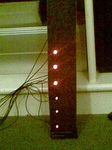
Step 7: Finished!
See pictures. Connect power, wire up an audio source, and plug in. Looking sexy!
Please comment.
Participated in the
The Instructables Book Contest


