

Introduction: Baqs: the Color-Changing Box
Baqs is a box that changes color based on its gyroscopic position. The x, y, and z axes of the box are obtained by a gyroscope module, and their values are used to set the intensity of the colors red, green, and blue. In addition to this, Baqs has a button that can be pressed to save a color on the box.
When the button is first pressed, the color will stay the same regardless of movement. Once the button is pressed again, the saved color will be placed at whatever gyroscopic position the box is held at. This means that the user can set any color to any location with just two button presses! The other colors work around the set color so that every movement has a smooth and logical color change.
Huge shout-out to Jrowberg for his libraries, and Tanishq Jaiswal for his tutorial, which was the foundation of this project. Tanishq Jaiswal's tutorial is here.
Step 1: Attach the Gyroscope Module (MPU6050) to the Arduino

Attach the following pins from the MPU6050 to the Arduino Nano. As you can see, I did this on a breadboard.
Vcc/Vdd----3V3
Gnd----GND
SCL----A5 (Analog 5)
SDA---A4 (Analog 4)
INT----D2 (Digital Pin 2)
IF you have the MPU6050 from sparkfun (like me) or you have a different chip that has a VIO pin, you must also attach the VIO pin to 3V3 in order to give it power.
Step 2: Download Necessary Code and Test Gyroscope


Jrowberg is responsible for creating the code necessary to read values on the gyroscope module. In order to use it, we need to download his libraries.
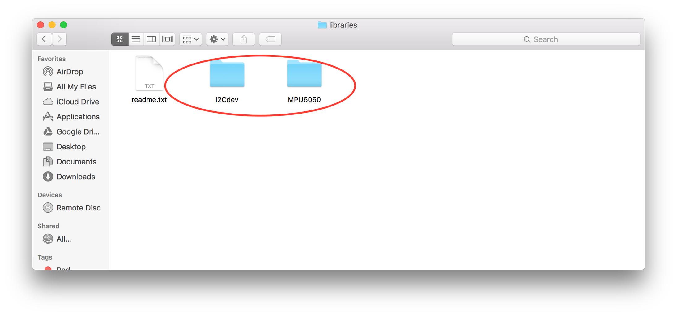
Visit this link, go to the section labeled arduino, and download the folders named "I2Cdev" and "MPU6050". Put these folders in the arduino library folder on your computer, and restart arduino.
If you've completed this successfully, there should be code labeled MPU6050 in examples.
Test the MPU6050_DMP6 code by loading it to your arduino. Open the serial monitor, and set the baud rate to 115200. If you see that the connection was successful and values appear, then it worked!
After doing all of this, go to this link and download the calibration sketch. Open it, run it, and record the serial monitor values for the gyroscope. ONLY the gyroscope.
Almost done with the code! Finally download the final sketch here. Enter your offsets in the area labeled to enter them. This code is now ready for the arduino.
Step 3: Set Up the LED

It's time to set up the RGB LED!
Put 3 transistors in your breadboard. Connect the three cathodes (Red, Blue, and Green) of the RGB LED to the right-most pin of each transistor (when facing the text on the transistor).
Connect the left-most pin of each transistor in series, and then connect them all to ground.
Connect one transistor to pin 9, one to pin 10, and one to pin 11.
Finally, connect the common anode of the RGB LED to a 220 ohm resistor, and then connect that to the VIN pin of the arduino.
Now, your RGB LED is ready.
Step 4: Wire Up the Button

The button is easily wired up. Simply connect the positive power supply to a 10K resistor. Then, connect that resistor to digital pin 4 as well as one of the button pins. Wire GND to the other button pin.
Step 5: Test

Test the code with your new setup. Everything should be in place, and it should work as described at the beginning of this tutorial. Move around your breadboard to see the LED change color, but make sure not to accidentally knock out and wires or alter the wiring in any way.
If you want to see angle values, go to the serial monitor and make sure the baud rate is 38,400.
If this doesn't work and you can't figure out why, feel free to email me at jordanmnunez16@gmail.com
Step 6: Solder


Time to solder it all together!
Use a prefboard and solder all of the connections you made on the breadboard onto the prefboard. If you want your arduino to be removable, I'd suggest using female headers and attaching your arduino to them.
Be mindful of where you put things on the board. You want to make it easy on yourself when soldering the wires and you also want to make sure that everything will be in the right place for the final product. The button must be in a place where it can be accessed from the outside of the box. I didn't solder the button into the prefboard, but rather soldered the button to wires that attached to the breadboard. This allowed me to put the button in a hole in the side of the box.
Check and double check your soldering!
Step 7: The Battery

The battery's positive end needs to be connected to VIN, and its negative end needs to be connected to ground. Make sure you have a way to disconnect the battery to charge it. I used a battery with a JST-PH connector, and soldered a receiving connector to VIN and GND.
Once the battery can be connected, you can test your Baqs just by connecting the battery. An on/off switch soldered somewhere might be fun to add, but I kept the project without an on/off switch because it is so easy to turn the project on and off by plugging and unplugging the battery.
Step 8: Make the Box


It's time to make the box. I used foam boards to make my box, but you can use whatever you are most comfortable with. My artistic friend helped me make this box look neat and professional.
As you can see, we made a platform to hold the prefboard in place. Make sure that you have a way to keep your prefboard in place when making the box.
Make a place for the button to be pressed!
We used tracing paper for the top of the box so that light would easily shine through, but the wiring would be kept hidden.

Participated in the
Microcontroller Contest 2017


