

Introduction: Build a 500 Metre Radio Data Link for Under $40.


Have a water tank you want to measure or a dam or a gate? Want to detect a car coming down the drive but don't want to string wires through the garden? This instructable shows how to send data 500 metres with 100% reliability using picaxe microcontroller chips and 315Mhz or 433Mhz radio modules.
Step 1: Schematic

The transmitter and receiver circuits are quite simple and use picaxe chips. These single chip microcontrollers can sense analog voltages, turn things on and off and can transmit data. See instructables https://www.instructables.com/id/Control-real-world-devices-with-your-PC/ and https://www.instructables.com/id/Worldwide-microcontroller-link-for-under-20/ for a description of how to program picaxe chips. With a radio link as well as an interface to a PC it is possible to sense data remotely and transmit it anywhere in the world.
Step 2: Transmitter and Antenna

The transmitter prototype was built on a piece of prototype board. There are a myriad of low power 10mW RF modules available which work well up to a range of about 30 metres. However, once the power goes up above half a watt the RF tends to get back into the picaxe chip and cause resets and other strange behaviour. The answer is to remove the module's antenna and take the RF away with 3 metres or more of 50ohm coax and build a proper dipole antenna. This also boosts the range considerably.
Step 3: Build a Dipole Antenna With a Balun

At the antenna is a balun made of coax cable. A balun is needed otherwise the shield of the coax ends up becoming an antenna instead of being the earth and radiates RF down near the picaxe which defeats the purpose of the antenna. There are lots of balun designs but I chose this one because it just uses bits of coax cable. Common wavelengths are 95.24cm for 315Mhz and 69.34cm for 433Mhz. The coax lengths are 1/4 and 3/4 of the wavelength respectively. The dipole wires are 1/4 of the wavelength. So for the modules I used at 315Mhz the coax wires were 23.8cm and 71.4cm and the dipole wires were each 23.8cm.
The coax shield and core are joined together where the coax splits into two. At the dipole note the shields are also connected. If these joins are out in the weather then they need to be weatherproofed in some way - eg with paint or non conductive silicone. Antennas work best when at least 2 metres off the ground.
Acknowledgement and thanks to I0QM for this design.
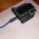
Step 4: Transmitter Module

The transmitter module is available on ebay for around $US14 at http://stores.ebay.com.au/e-MadeinCHN. The current consumption is around 100mA when transmitting at 9V, and is virtually nothing when idle. The antenna was removed to build the dipole, though the module might be ok with the antenna attached if it were paired with a different microcontroller. The coax braid is connected to the module earth which is conveniently next to the antenna connection.
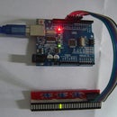
Step 5: Receiver Module

The receiver module is a superheterodyne unit available for around $US5 from the same ebay store. There are a number of other modules (including superregenerative) that are not as sensitive and don't give the range.
Step 6: Receiver Circuit and Picaxe Code

The receiver module is connected to a picaxe as shown in the schematic. The antenna is a 23.8cm piece of wire, and to make a dipole and increase the sensitivity another length of 23.8cm wire is soldered to the earth of the module.
The transmitter code is as follows:
main:serout 1,N2400,("UUUUUUUUUUUUUTW",b0,b1,b2,b3,b4,b5,b6,b7,b8,b9,b10,b11,b12,b13)
' T and W = ascii &H54 and &H57 = 0100 and 0111 = equal 1s and 0s
'b0=random number
'b1=random number
'b2=to device
'b3=reverse
'b4=messagetype
'b5=reverse
'b6/b7 = data 1 and reverse
'b8,b9 = data 2
'b10,b11 = data 3
'b12,b13 = data 4
random w0 ' random number used to identify messages when using multiple repeaters
b2=5' to device number...
b3=255-b2
b4=126' random number for testing
b5=255-b4
b6=0' random number for testing
b7=255-b6
b8=1' random number for testing
b9=255-b8
b10=2' random number for testing
b11=255-b10
b12=3' checksum - any value
b13=255-b12
pause 60000' transmit once per minute
goto main
And the receiver code:
main: serin 4,N2400,("TW"),b0,b1,b2,b3,b4,b5,b6,b7,b8,b9,b10,b11,b12,b13
b13=255-b13' inverse again only need to really test one
if b12=b13 then
for b12=0 to 55
high 2
pause 100' flash led once a second for a minute
low 2
pause 900
next
endif
goto main
The transmitter sends a packet once per minute - once debugged this ought to be decreased to every 15 mins or 30mins to avoid interference to neighbours. The "ÂUUUU"Â at the beginning of the packet is binary for 01010101 which balances the Rx unit. The protocol uses a form of Manchester coding where the number of 1's and 0's is kept as equal as possible, and this is done by sending the inverse of each byte after the byte is sent. Without this the packets sometimes don't get through if they are sending lots of binary zeros. A checksum at the end must be valid before the data is processed. The receiver flashes a led for 55 seconds when a packet is received and once debugged, this could be changed to some other acknowledgement.
Step 7: Lower Power Module and Neighbourly Relations

To keep neighbourly relations happy, especially with digital TV, send the data as far as it needs to go but no further. One can argue about the legalities of higher power transmitters but the best solution is to keep the RF on your property and send data infrequently in brief packets. This lower power module is half the price and goes about 200 metres. The lower power does have the advantage that it can have an antenna mounted directly on the module and can be soldered next to the picaxe, so the coax and balun are not needed.
Range tests were done through trees and over a hill which explains why a module listed as "4000m" only went 500 metres.
Next up will be an instructable on building self contained solar power supplies suitable for the these units, as well as sensors such as temperature, pressure, humidity, soil moisture and tank levels.


