

Introduction: Build an Arduino Atmega 328P Micro Controller on a Breadboard or a Prototyping Board


Here I will show you how to build a micro controller on a breadboard or a prototyping board.
You may want to do this if you would like to make your project permanent and or smaller.
I have read a few instructions some are easier to understand then others, I will try to make a beginner guide. Something easy to understand.
Step 1: Parts.
Per programed Atmega 328P-PU with bootloader
Some sort of Voltage regulator (I'll use a 7805CV 5 volt regulator) I will talk more about regulators later...
Breadboard to start and test, Don't forget you will need jumpers or wires for the breadboard. This kit come with both
Prototyping board after testing and to make permanent
Step 2: Lets Look at the Pin Out of the Atmega328P
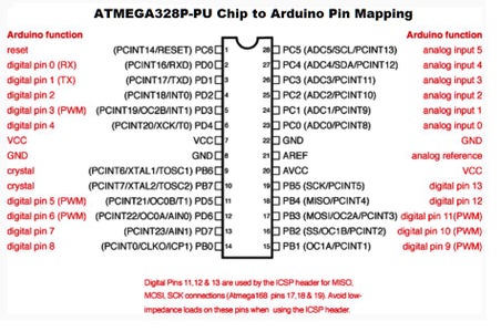
Pin 1 = for resetting the micro controller.
Pin 2 = Digital pin 0 (RX = receive)
Pin 3 = Digital pin 1 (TX = transmit)
Pin 4 = Digital pin 2
Pin 5 = Digital Pin 3
Pin 6 = Digital pin 4
Pin 7 = VCC (+5VDC)
Pin 8 = GND (Ground)
Pin 9 = Crystal (16mHZ)
Pin 10 = Crystal (16mHZ)
Pin 11 = Digital pin 5
Pin 12 = Digital pin 6
Pin 13 = Digital pin 7
Pin 14 = Digital pin 8
Pin 15 = Digital pin 9
Pin 16 = Digital pin 10
Pin 17 = Digital pin 11
Pin 18 = Digital pin 12
Pin 19 = Digital pin 13
Pin 20 = VCC (+5VDC)
Pin 21 = Analog Reference (+5VDC)
Pin 22 = GND (Ground)
Pin 23 = Analog input 0
Pin 24 = Analog input 1
Pin 25 = Analog input 2
Pin 26 = Analog input 3
Pin 27 = Analog input 4
Pin 28 = Analog input 5
Step 3: Schematic for You Breadboard
Start by inserting you Atmega 328P in to the breadboard
Then connect the crystal to Pins 9 and 10
Then add you 22pF capacitors to pin 9 and ground and another one the pin 10 and ground
Then connect Pins 8 and 21 to ground
Then Connect Pin 8 20 and 21 to +5VDC
Than connect Pin 1 to a 10K resistor and to +5VDC
Next step we will work on the Power regulator to power the Atmega 328P
Step 4: Regulators...
Different types of regulators
5 volt regulator like the 7805CV
- Variable regulators like a LM317
- Buck Converter or Step-Down Converter
Lets talk about a 7805CV Datasheet
The 7805CV Will take a + voltage from +5VDC to +18VDC and convert it to +5VDC
Pro:
input voltage can vary and you will still have +5VDC on the output as long as the input voltage doesn't drop below +5VDC. Will work will with battery's
Con:
Gives off heat. If you have you circuit in a small enclosed space you may over heat the 7805CV and cause it to turn off.
The LM317 Datasheet
The LM317 Will take + voltage from +1.25DC to +37VDC. You will need at lest +9VDC to convert it to +5VDC.
Pro:
Cheaper then a 7805CV. Would work best with a AC to DC adapter
Con:
You will always need a steady in put voltage if your input voltage drops your output voltage will drop. Gives off heat. If you have you circuit in a small enclosed space you may over heat the 7805CV and cause it to turn off.
A Buck converter
Will take a wide variety of in put voltage and out put +5VDC.
Pro:
Unlike the LM317 you can put +5VDC in and still get +5VDC out but if the input voltage drops your output voltage will also drop. The most energy efficient. When ever you create heat you are loosing energy. If your input Voltage drops you can adjust the potentiometer (variable resistor) to increase your output voltage until your input voltage drops below +5VDC.
Con:
Like a 7805CV You will need a steady in put voltage if your input voltage drops your output voltage will drop. Most expensive.
Step 5: 7805CV
Page 3 of the Datasheet will show you the pin out of the mosfet
from left to right
Pin 1 = input voltage (=5VDC to +18VDC)
Pin 2 = Ground (from input and to output)
Pin 3 = Output voltage (+5VDC)
Connect a 10uf capacitor to Pin 1 and Pin 2
Also connect a 10uf Capacitor to Pin 2 and Pin 3


