

Introduction: Capacitance Meter With Arduino and 555 Timer


CAPACITANCE METER WITH ARDUINO AND 555 TIMER CHIP
This project aims to build a simple capacitance meter, a device for measuring capacitance in nanoFarads and microFarad, with a range of about 1 nanoFarad to hundreds of microFarads.
This project, my first instructable, is based on the characteristics of the well known 555 timer ic, configured as a monostable multivibrator.
The 555 as monostable
In this mode, the 555 is used to produce an output pulse whose duration can be determined by the choice of a resistor and a capacitor using a very simple formula as the Ohm's law itself:
T = 1.1 x R1 x C1
This formula allows us to calculate the capacitance:
C1 = T / (1.1 x R1)
And as R1 is known (we have chosen it), we only need to know the value of T (pulse duration).
This is where the Arduino enters the game, having the mission to determine T, calculate C1 and inform us the results through the serial port.
Step 1: BRIEF EXPLANATION OF THE 555 IN MONOSTABLE CONFIGURATION

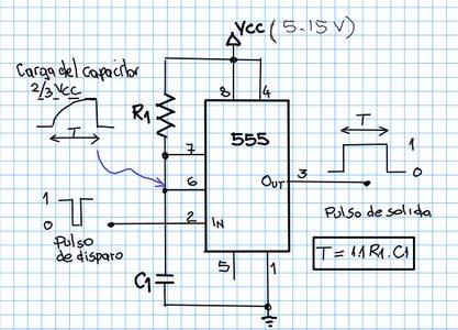
555 OPERATION AS MONOSTABLE (see figure above)
The process begins when a trigger pulse is applied to the input terminal (2) of the 555 that carries its voltage level below 1/3 VCC; this fires a pulse at the output (3) from low (0) to high (VCC).
At the same time the charging process of the capacitor begins according to the well known exponential low of the charging of capacitors.
When the charge reaches the level of 2/3 VCC, the output returns to low marking the end of the pulse.
The pulse duration corresponds to the value determined with the above-described formula.
T = 1.1. R1.C1
Step 2: THE FUNCTION OF THE ARDUINO

ARDUINO FOR MEASURING THE PULSE WIDTH
The output (3) of the 555 is connected to the arduino (for this project I used the arduino one) at two of its terminals (2 and 3) which are programmatically attached to the interrupts 0 and 1 to enable them to detect changes of the voltage level at the 555 output terminal.
So the pin 2 which is linked to Interrupt 0 will detect the RISING edge of the output pulse and instantly stop (interrupt) all activity that was taking place at that moment and arduino executes the code in the function Start() that we wrote.
The code in the Start() function just save the time returned by the millis() function in a volatile (global) variable. An led is also turned on here to give a visual sign that the interrupt took place. Then the function ends and so does the interrupt.
Then, when the 555 output pulse ends, the arduino pin 3 which is linked to the interrupt 1 detects its FALLING edge triggering another interruption in the operation of the arduino to execute now the code in another function which we called Stop(). As in the Start() function, the code here just set another volatile variable (t_final) with the value returned by the millis() function and turns the led off, marking the end of the pulse.
The code in the Loop () function is responsible for continuously verifying whether the value of the variable t_final is no longer zero, event that will happen at the end of the pulse.
When the condition in our if block confirms that t_final is effectively no longer 0, the code proceeds to the determination of T (the pulse duration) and with it the capacitance is calculated.
T = T_final - T_inicial
C1 = T / (1.1 x R1)
In the schematic of the circuit we can see the values of the components used.
1 Mohm for R1 is suitable for capacitors in the range of about 1 nF to 1uF.
Higher values of capacitance will cause durations of pulses of several seconds, so in the case of measuring these values it would be advisable to use a 1 kohm resistor.
Step 3: BUILDING THE CIRCUIT

In the image above you can see the circuit mounted on a breadboard. It is very simple and easy to implement.
You can also click the .ino file to see the source code.
The circuit is powered by the arduino itself (VCC = + 5V).
The trigger circuit comprises a switch in conjunction with a 1k resistor and a 100nF capacitor.
The capacitor in the terminal 5 (CV) of 555 is not required for this project.
I hope this instructable can be useful to someone, especially because despite its simplicity arduino advanced topics are covered (interrupts).
It also lets us know a bit more about the so versatile the 555 timer.
Until the next instructable. See you...


