Introduction: Contactless IoT Thermometer
The COVID-19 pandemic has spread to most parts of the world like a wildfire. One of the most telling symptoms of the infection includes fever, dry cough, and breathlessness. Now, 95% of cases of the virus have mild symptoms that can be treated and handled at home with proper quarantine precautions. For people who have mild symptoms or are still asymptomatic but fear having been in contact with the virus, the advice given by doctors is that they need to measure their temperature at least twice a day and monitor it to help determine if they are getting better or worse.
The thermometer is the most accurate way to tell if you are running a fever or not. An infrared thermometer can give you the temperature instantly. You can find a contactless infrared thermometer in the online markets but no one supports IoT functionality so keeping the record of the temperature is not easy. To solve this problem I made this IoT thermometer which sends the data to the cloud server automatically when measured and the graph can be visualized from the web dashboard.
Features:
- 1. Contactless
- 2. Rechargeable
- 3. WiFi Enabled and store the data to the cloud
- 4. Data can be visualized from a graph
- 5. Auto power-saving mode
- 6. Dual scale and configurable
Video Demo
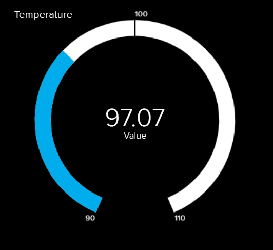
Dashboard Graph from Adafruit.io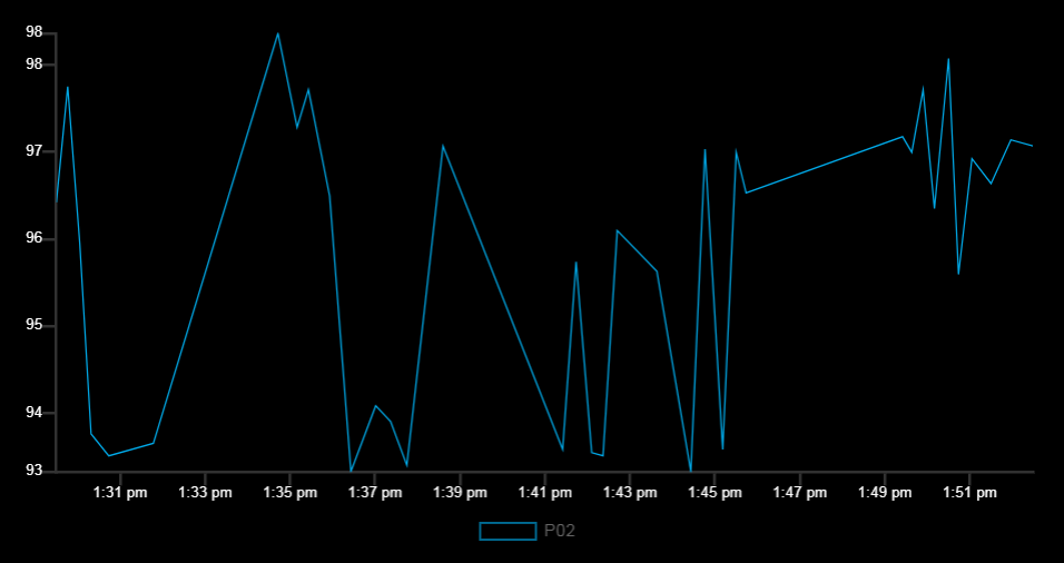
Supplies
Components:
1. MLX90614 IR temperature sensor module (AliExpress.com Product - MLX90614 non-contact infrared temperature sensor module I2C Interface GY-906): MLX90614 sensor is manufactured by Melexis Microelectronics Integrated system, it has two devices embedded in it, one is the infrared thermopile detector (sensing unit) and the other is a signal conditioning DSP device (computational unit). It works based on Stefan-Boltzmann law which states that all objects emit IR energy and the intensity of this energy will be directly proportional to the temperature of that object. The sensing unit in the sensor measures how much IR energy is emitted by a targeted object and the computational unit converts it into temperature value using a 17-bit in-built ADC and outputs the data through I2C communication protocol. The sensor measures both the object temperature and ambient temperature to calibrate the object temperature value.

2. Wemos D1 mini ESP8266 (buy from gearbest.com): Wemos D1 mini is like a "little Arduino with wifi" for a great price. It's based around the ESP8266, has one analog port and 11 digital ports. It's programmed via micro-USB (or remote flash via wifi). You can use it with the Arduino IDE, micropython or NodeMCU. The WeMos D1 min PRO is a miniature wireless 802.11 (Wifi) microcontroller development board. It turns the very popular ESP8266 wireless microcontroller module into a fully-fledged development board. Programming the D1 mini pro is as simple as programming any other Arduino based.
3. 0.96 inch OLED display (buy from gearbest.com): The organic light-emitting diode (OLED) display that we’ll use in this tutorial is the SSD1306 model: a monocolor, 0.96-inch display with 128×64 pixels resolution. The OLED display doesn’t require backlight, which results in a very nice contrast in dark environments. Additionally, its pixels consume energy only when they are on, so the OLED display consumes less power when compared with other displays.
The model we’re using here has only four pins and communicates with the Arduino using I2C communication protocol.
4. 18650 Li-ion battery (buy from gearbest.com): The 18650 battery is a lithium-ion cell classified by its 18mm x 65mm size, which is slightly larger than a AA battery. They’re often used in flashlights, laptops, and high-drain devices due to their superior capacity and discharge rates. 18650s come in both flat and button top styles, and usually boast 300-500 charge cycles.
5. TP4056 1A Li-ion lithium Battery Charging Module (buy from gearbest.com): The TP4056 1A Li-Ion Lithium Battery Charging Module – Micro B USB is a 3.7V lithium battery charger module has on-board Micro USB interface. With Micro-USB onboard connector, you can directly connect to computer USB port for battery charging. If USB is not available you can use an external source voltage at IN+/IN- pads, great for DIY projects. It is small size and lightweight. This module is made for charging rechargeable lithium batteries using the constant-current/constant-voltage (CC/CV) charging method. In addition to safely charging a lithium battery the module also provides necessary protection required by lithium batteries. See below concerning the protection features this module provides.
6. 6*6 mini tactile button (4pcs), perf board, and jumper wires.
Tools
1. Generic 3D Printer: I use Anet A8, a low price excellent quality 3D printer. I am using this printer for about 3 years and I am very much satisfied with the performance of the printer. You can buy Anet A8 from Gearbest for $170. The printer is available in Kit form and buying this you can get the pleasure of building a 3D printer yourself.
2. A soldering Station: You can buy this adjustable temperature soldering station from Gearbest.com for $42 at 36% discount. It has rapid heating and rewarming capacity and especially suitable for lead-free soldering and soldering.
3. Wirecutter.
Step 1: 3D Designing & Printing
After collecting the components you need to print the 3D files. All the required files are attached here. The original design was collected from Thingiverse (https://www.thingiverse.com/thing:4298489). Thanks to Mr. ASHISH PARDESHI for his nice design. I modified the design using Tinkercad. The original design was made for 9V battery, I modified it for 18650 Li-ion rechargeable battery.
I printed all the files using my Anet A8 3D printer I bought from Gearbest.com before 3 years ago. It is an excellent 3D printer at a low cost.
Step 2: Making Display & Control Board
After printing all the files the first work is to prepare the control board with the display. I first soldered three mini tactile buttons for configuration and setting functionality. A perf board should be cut according to the size of the front panel which is (28mm X 48mm). Then according to the button cut solder the buttons. No pull up resistor is required because the internal pull-up resistor will be used from the program. One terminal of all the switches should be connected together which needs to be connected to the ground on a later step.
Step 3: Connecting the Display & Trigger Button
After connecting the buttons the next work is to place the display on the perf board. A separate perf board was prepared for placing the Wemos D1 board into it using female pin headers. display cable and the jumpers from the button boards need to be connected to the female headers according to the schematic. Then we need to connect another button to the board which will be used to measure and upload the data to the cloud.
Step 4: Connecting Battery Spring
We are going to use a 18650 Li-ion rechargeable battery for our thermometer. We will place the battery inside the handle of the thermometer. As we are not using an external battery case for our battery we need to place two battery spring inside the room of the battery. The springs need to be connected to a battery charger circuit through the jumper wires. The battery management circuit helps to charge and protects the battery from overcharging and protects the battery from burning.
Step 5: Placing the Battery Charger Circuit
After connecting the charger circuit to the battery spring using jumper wires the next work is to place the battery charger circuit to the right place. The figure shows the placing of the charger circuit to the right place. It also shows the placing of the spring and the wires.
Step 6: Connecting the Power Wires
To power, wires should bring out from the charger circuit to the controller circuit. Charger circuit has the OUT + and OUT - marking which will be used to provide the power to the controller board.
Step 7: Connecting Power Switch
The battery was placed to the bottom part of the case. A power button will be placed to the top part of the case. The top part has a place for fixing the power switch. An SPDT switch is placed to the top part and connected with the battery out. This switch will be used to turn on and off the device.
Step 8: Connecting & Uploading Arduino Sketch
All the soldering is completed. Now it is the right time to place and fixed all the PCB and sensor to the right part. The front panel board should be fixed with the front side of the printed part. I used hot glue to fix it tightly with the printed plate. The sensor should be placed in the front panel and should be fixed using glue. After placing all the parts we need to upload the sketch and test everything is working.
Before uploading the code you need to prepare your Adafruit IO account. Read this guide if you are new. https://learn.adafruit.com/welcome-to-adafruit-io/...
/* This code works with MLX90614 (GY906) and OLED screen
 * It measures both ambient and object temperature in Fahrenheit and display it on the screen
 *
 *
 *
 */
#include <Wire.h>
#include <Adafruit_GFX.h>
#include <Adafruit_SSD1306.h>
#include <Fonts/FreeSerif12pt7b.h>
#include <Fonts/FreeMono9pt7b.h>
#include <Fonts/FreeSerif9pt7b.h>
#include <Adafruit_MLX90614.h>
#include "AdafruitIO_WiFi.h"
#include <EEPROM.h>
#include "Arduino.h"

#define IO_USERNAME "Your Adafruit IO Username"
#define IO_KEY "Your Adafruit IO Key"
#define WIFI_SSID "your wifi ssid"
#define WIFI_PASS "your wifi password"
#define SCREEN_WIDTH 128 // OLED display width, in pixels
#define SCREEN_HEIGHT 64 // OLED display height, in pixels
#define OLED_RESET    -1 // Reset pin # (or -1 if sharing Arduino reset pin)

#define MENU D5
#define UP D6
#define DOWN D7
#define MEASURE D4

int menu = 0;
int celcius = 0;
int wifi = 1;
int body_temp = 1;
int patient_id = 1;
int display_on = 1;


Adafruit_SSD1306 display(SCREEN_WIDTH, SCREEN_HEIGHT, &Wire, OLED_RESET); //Declaring the display name (display)
Adafruit_MLX90614 mlx = Adafruit_MLX90614();
AdafruitIO_WiFi io(IO_USERNAME, IO_KEY, WIFI_SSID, WIFI_PASS);
//AdafruitIO_Feed *temperature = io.feed("temperature");

void setup() {

  pinMode(MENU, INPUT_PULLUP);
  pinMode(UP, INPUT_PULLUP);
  pinMode(DOWN, INPUT_PULLUP);
  pinMode(MEASURE, INPUT_PULLUP);

  /************************Read Configuration fromEEPROM***************************/
  EEPROM.begin(512);  //Initialize EEPROM
  celcius = EEPROM.read(0);
  wifi = EEPROM.read(1);
  body_temp = EEPROM.read(2);

  mlx.begin();
  display.begin(SSD1306_SWITCHCAPVCC, 0x3C); //Start the OLED display

  home_page();

  Serial.begin(9600);
  delay(10000);
  // connect to io.adafruit.com
  if(wifi)connectAIO();
  if(io.status() < AIO_CONNECTED){
    display.clearDisplay();
    display.setTextColor(WHITE);
    display.setTextSize(1);
    display.setFont();
    display.setCursor(0,20);
    display.println("No Internet Access!");
    display.display();
    delay(3000);
    }

  // we are connected
  Serial.println();
  Serial.println(io.statusText());

}

long time_count = millis();
void loop() {

  if(!digitalRead(MENU)){
    time_count = millis();
    delay(200);
    menu++;
    if(menu>3) {
       menu = 0;
       EEPROM.write(0, celcius);
       EEPROM.write(1, wifi);
       EEPROM.write(2, body_temp);
       EEPROM.commit();
      }
    }

  if(!digitalRead(UP)){
    time_count = millis();
    delay(200);
    if(menu==0) patient_id++;
    if(menu==1) celcius = 1;
    if(menu==2) wifi = 1;
    if(menu==3) body_temp = 1;
    }

  if(!digitalRead(DOWN)){
    time_count = millis();
    delay(200);
    if(menu==0) patient_id--;
    if(menu==1) celcius = 0;
    if(menu==2) wifi = 0;
    if(menu==3) body_temp = 0;
    }

  if(wifi){
    if(WiFi.status() != WL_CONNECTED){
       WiFi.forceSleepWake();
       delay(1);
       WiFi.mode(WIFI_STA); //
       WiFi.begin(WIFI_SSID, WIFI_PASS); //
       while (WiFi.status() != WL_CONNECTED) {
         delay(500);
         Serial1.print(".");
        }
      }
    }

  if(!wifi){
      WiFi.disconnect(); //
      WiFi.mode(WIFI_OFF);//
      WiFi.forceSleepBegin();
      delay(100);
    }

  if(menu == 0) home_page();
  else if(menu == 1) scale_setup_page();
  else if(menu == 2) wifi_setup_page();
  else if(menu == 3) temp_setup_page();

  if(!digitalRead(MEASURE)){
    time_count = millis();
    display.ssd1306_command(SSD1306_DISPLAYON);
    display_on = 1;
    Serial.println("Button Press");
    delay(5000);
    if(wifi){
    if(io.status() >= AIO_CONNECTED){temp_write();
    display.clearDisplay();
    display.setTextColor(WHITE);
    display.setTextSize(1);
    display.setFont();
    display.setCursor(0,20);
    display.println("Data Sent!");
    display.display();
    delay(1500);
    }
    else{
    display.clearDisplay();
    display.setTextColor(WHITE);
    display.setTextSize(1);
    display.setFont();
    display.setCursor(0,10);
    display.println("No Internet access!");
    display.display();
    delay(1500);
      }
     }
    //delay(3000);
    }

  if((millis()>= time_count + 50000) && display_on == 1){
    display.ssd1306_command(SSD1306_DISPLAYOFF);
    display_on = 0;
    }

  //display.ssd1306_command(SSD1306_DISPLAYON);
  //io.run();
  //temperature->save(tempF);
  //delay(3000);

}

void home_page(){
  float body_tempF = mlx.readObjectTempF()+ 4.5;
  float ambient_tempF = mlx.readAmbientTempF();
  float body_tempC = (body_tempF-32)/1.8;
  float ambient_tempC = (ambient_tempF-32)/1.8;
  display.clearDisplay();
  display.setTextColor(WHITE);
  display.setTextSize(1);
  display.setFont();
  display.setCursor(0,0);
  if(body_temp)
    display.println("Body Temperature");
  else
    display.println("Ambient Temp");
  display.setFont(&FreeSerif12pt7b);
  display.setCursor(20,40);
  if(body_temp && celcius) display.println(body_tempC,2);
  else if(body_temp && !celcius) display.println(body_tempF,2);
  else if(!body_temp && !celcius) display.println(ambient_tempF,2);
  else if(!body_temp && celcius) display.println(ambient_tempC,2);
  //display.println(mlx.readObjectTempF()+4.5,2);
  display.setCursor(80,40);
  display.drawCircle(85, 28, 3, WHITE);
  if(celcius) display.println("  C");
  else display.println("  F");
  display.setFont();
  display.setCursor(0,55);
  display.print("ID: P0");
  display.println(String(patient_id));
  display.setCursor(70,55);
  if(WiFi.status() == WL_CONNECTED) display.println("WiFi: ON");
  else display.println("WiFi: OFF");
  display.display();
  }


void scale_setup_page(){
  display.clearDisplay();
  display.setTextColor(WHITE);
  display.setFont(&FreeSerif9pt7b);
  display.setCursor(0,13);
  display.println("Temp Scale");
  display.setFont(&FreeSerif12pt7b);
  display.drawCircle(65, 25, 3, WHITE);
  display.drawRect(35, 25, 15, 15, WHITE);
  display.setCursor(70,39);
  display.println("C");
  display.drawCircle(65, 45, 3, WHITE);
  display.drawRect(35, 45, 15, 15, WHITE);
  display.setCursor(70,60);
  display.println("F");
  if(celcius)
    display.fillRect(37, 27, 11, 11, INVERSE);
  else
    display.fillRect(37, 47, 11, 11, INVERSE);
  display.display();
  }


void wifi_setup_page(){
  display.clearDisplay();
  display.setTextColor(WHITE);
  display.setFont(&FreeSerif9pt7b);
  display.setCursor(0,13);
  display.println("WiFi Setup");
  display.setFont(&FreeSerif12pt7b);
  display.drawRect(10, 25, 15, 15, WHITE);
  display.setCursor(40,39);
  display.println("Enable");
  display.drawRect(10, 45, 15, 15, WHITE);
  display.setCursor(40,60);
  display.println("Disable");
  if(wifi)
    display.fillRect(12, 27, 11, 11, INVERSE);
  else
    display.fillRect(12, 47, 11, 11, INVERSE);
  display.display();
  }

void temp_setup_page(){
  display.clearDisplay();
  display.setTextColor(WHITE);
  display.setFont(&FreeSerif9pt7b);
  display.setCursor(0,13);
  display.println("Temperature");
  display.setFont(&FreeSerif12pt7b);
  display.drawRect(10, 25, 15, 15, WHITE);
  display.setCursor(40,39);
  display.println("Body");
  display.drawRect(10, 45, 15, 15, WHITE);
  display.setCursor(40,60);
  display.println("Ambient");
  if(body_temp)
    display.fillRect(12, 47, 11, 11, INVERSE);
  else
    display.fillRect(12, 27, 11, 11, INVERSE);
  display.display();
  }

void power_saving_mode(){
   display.ssd1306_command(SSD1306_DISPLAYOFF);
   //wifi_station_disconnect();
   wifi_set_opmode(NULL_MODE);
   wifi_fpm_set_sleep_type(LIGHT_SLEEP_T);
   wifi_fpm_open(); // Enables force sleep
   //wifi_fpm_set_wakeup_cb(callback);
   gpio_pin_wakeup_enable(GPIO_ID_PIN(MEASURE), GPIO_PIN_INTR_LOLEVEL); // GPIO_ID_PIN(2) corresponds to GPIO2 on ESP8266-01 , GPIO_PIN_INTR_LOLEVEL for a logic low, can also do other interrupts, see gpio.h above
   wifi_fpm_do_sleep(0xFFFFFFF); // Sleep for longest possible time
  }

void callback() {
  display.ssd1306_command(SSD1306_DISPLAYON);
  Serial1.println("Callback");
  Serial.flush();
}

void temp_write(){
   // set up `deepsleep` feed
  String str = "P0";
  str += patient_id;
  int str_len = str.length() + 1;
  char char_array[str_len];
  str.toCharArray(char_array, str_len);
  AdafruitIO_Feed *temperature = io.feed(char_array);
  Serial.println("sending temperature to feed");
  float body_tempF = mlx.readObjectTempF()+ 4.5;
  float ambient_tempF = mlx.readAmbientTempF();
  float body_tempC = (body_tempF-32)/1.8;
  float ambient_tempC = (ambient_tempF-32)/1.8;

  if(body_temp && celcius) temperature->save(body_tempC,2);
  else if(body_temp && !celcius) temperature->save(body_tempF,2);
  else if(!body_temp && !celcius) temperature->save(ambient_tempF,2);
  else if(!body_temp && celcius) temperature->save(ambient_tempC,2);
  // send data to deepsleep feed
  //temperature->save(temp);
  // write data to AIO
  io.run();
}

void connectAIO() {
  Serial.println("Connecting to Adafruit IO...");
  io.connect();
  long entering_time = millis();
  // wait for a connection
  while ((io.status() < AIO_CONNECTED) || (millis()> entering_time + 15000)) {
    Serial.print(".");
    delay(500);
  }

  // we are connected
  Serial.println();
  Serial.println(io.statusText());
}
Step 9: Assembling the Device
After uploading and testing the final work is to assemble the device. If after uploading the code everything goes well, place the battery to the battery holding unit. After placing the battery we need to connect the bottom part with the top part. Then we need to connect the sensor panel and the display panel with the body. Finally, we need to add the screw to tightly connect all the parts together. If you completed all the work then your device is ready to enjoy.

Participated in the
Arduino Contest 2020


