

Introduction: Customizable IR Remote Replacement -- No Android Programming Required


Update 1st Dec 2022: As well as the free pfodDesignerV3 Android app for menu design, there is now also a free pfodGUIdesigner Android app to design interactive GUI components
Updated 2nd February 2018 – Revised IR capture sketches for improved accuracy and compatibility with AnalysIR
This is a DIY Universal multi IR remote control run via WiFi from customizable buttons on your Android mobile. No Android Programming is required.
This Arduino project uses your Android mobile to replace multiple IR controls via WiFi. You place the USB powered Wifi_IR_Remote box near your Audio-video equipment and run the two IR led leads to the front of the equipment and fix them pointed at the equipment's IR receivers. The IR leds have a +/-25deg half power spread so one led can cover a number of devices in a stack. We use one IR led for the TV and the other for the stack of PVR's DVD's etc.
The Android screen layout, button size, colour, labels, what IR codes are assigned to which buttons and which buttons repeat, and how quickly they repeat, are all completely controlled by your Arduino code. None of the screens shown here are hard coded into your Android mobile.. The general purpose pfodApp is used to render the screens based on the messages your Arduino code sends.
This Wifi IR Remote is very customizable:-
- You can combine the functions of two, or more, remotes on one screen.
- You can add explanatory labels, and even on screen popup help messages, to suit your user's needs and assist them is using the controls they need.
- You can give important buttons emphasis with size, colour and position.
- You can control which buttons have a repeat function if held down and how quickly they repeat.
- Any Android mobile with pfodApp installed can display the user interface.
- You can code your own macros for common button combinations.
- It is powered via a USB cable (500mA max) and so can be plugged into a spare USB socket on your TV or PVR.
- To simplify connecting to your home WiFi network there is a push button that serves a configuration web page where you can fill in your network's details.
Tip: If you listen to and implement the feedback from your users, you will end up with a remote control that tailored to what they actually want to use, with the commonly used buttons grouped together with meaningful labels and with the important buttons given prominence
pfodApp can connect via WiFi, Bluetooth, Bluetooth Low Energy and SMS. In this project the connection is via WiFi and a web page network configuration is include in the code to simplify setting up.
These instructions are also on-line, Customizable IR Remote Replacement
Step 1: Why This Project?
This was a rushed project I had to get running in a few days. The IR controller for our Beyondwiz PVR (Programmable Video Recorder) started to fail and replacements were no longer available. While laying out the Android screen display, the family had wanted a commonly used buttons grouped together. It turned out that a few of the TV controls like Power, AV input selection, Mute and Volume control were regularly used together with the PVR. With this project it was easy to combine those buttons from the multiple controls on the same screen in the order and with the prominence requested.
This project covers both recording of an existing control as well as some tips for using IR codes documented in a manual. If you don't have a working controller and don't have a manual with the codes then http://lirc-remotes.sourceforge.net/remotes-table... may have your model listed OR you may be able to find a Universial IR Remote that will control your device and then record the codes from it.
If you use http://lirc-remotes.sourceforge.net/remotes-table... then check outhttp://www.righto.com/2010/03/understanding-sony-ir-remote-codes-lirc.html for details on how to convert those code files to something the IRremote library can use. You may have to write your own IRsend::send... for your particular remote's timings. For a Windows version of LIRC see http://lirc-remotes.sourceforge.net/remotes-table... and also check out its Links section. WinLIRC has an option to view the IR signal. The AnalysIR program used here has an option to import LIRC files.
See http://lirc-remotes.sourceforge.net/remotes-table... for a linux program to convert LIRC to CCF (Pronto format) raw signals. See http://lirc-remotes.sourceforge.net/remotes-table... for a description of CCF format which is related to, but not the same as, the 'raw' format recorded here.
The project has a number of components:-
- An IR recorder to record/decode/compress the codes from your existing remotes (using the TeensyLC)
- An IR transmitter to send recorded code (using the TeensyLC)
- A Wifi pfodDevice to serve the screen layout to your Androd mobile (running pfodApp) and to handle you button presses (using the ESP8266)
- A Wifi Access Point and web server to serve the network configuration web page to connect the Wifi_IR_remote to your network (using the ESP8266)
Step 2: Construction


TIP: Build two of these devices, because once you install one, the family will want changes made, but will not want to give up the device while you make and test the changes. The construction is designed to make it easy to swap the Wifi_IR_Remotes.
Parts List
Cost (one unit) ~US$78 as at 20th Jan 2018, excluding shipping and the heavy duty double sided tape. The second unit's cost is ~US$43, as you won't need to duplicate the pfodApp and AnalysIR.
- TeensyLC – ~US$12 https://www.pjrc.com/teensy/teensyLC.html
- Adafruit HUZZAH ESP8266 Breakout – ~US$10 https://www.adafruit.com/product/2471
- 1 x TSMP58000 – ~US$1 www.digikey.com Digikey Part No TSMP58000-ND
- 2 x TSAL6400 IR transmitter (25 deg) – ~US$1 www.digikey.com Digikey Part No 751-1205-ND
- Momentary push button, normally open – ~AUD$1 e.g. Multicorp TM-533I-Q-T/R http://au.element14.com/multicomp/tm-533i-q-t-r/s...
- 470uF 16V Low ESR capacitor – ~US$0.50 e.g. www.digikey.com Digikey Part No 493-15233-1-ND or Jaycar RE6314
- Vero board (>83mm x >55mm) – ~AUD$5 e.g. https://www.jaycar.com.au/universal-pre-punched-e...
- USB A to Micro B cable – ~US$4 https://breadfruit/product/2008 (3 foot long) OR~US$3 https://breadfruit/product/2008 (6 inches long) OR ~US$2 https://www.sparkfun.com/products/13244 (6 inches long) OR ~US$5 https://www.sparkfun.com/products/13244 (6 foot long) OR similar
- Heavy Duty Double Sided Tape – ~US$8 e.g. Scotch Heavy Duty Clear Mounting Tape
- 2m Figure 8 cable – ~US$2 e.g. https://www.jaycar.com.au/medium-duty-fig-8-speak...
- Header - 6-pin Female – ~US$0.5 e.g. https://www.sparkfun.com/products/11894
- Break Away Male Headers - Right Angle – ~US$2 e.g. https://www.sparkfun.com/products/553
- pfodApp – ~US$10 (one licence can be used by multiple family members)
- AnalysIR – ~US$25 Arduino IDE V1.8.5 and a computer to run it on.
- For a plastic box I used one from Jaycar UB5 (clear) 83mm x 54mm x 31mm ~A$4
Why Teensy plus HUZZAH ESP8266 Breakout?
Since this was a rush project, I took the path of least resistance. I already had a Wifi Shield from the the Cheap/Simple Wifi Shield and had a TeensyLC from another previous project. Also when you install Teensyduino (the Teensy Arduino IDE addon), the install offers you the option of installing the IRremote library ready to run on TeensyLC. Both these boards have compatiable 3.3V I/O.
Having two processors also simplifies testing and debugging. The ESP8266 handles the pfodApp display and the WiFi messages, and sends two character commands to the TeensyLC via RS232 at 115200 baud. The TeensyLC takes the command and looks up the associated IR code and sends it. Both boards have their own on board 5V to 3.3V regulators so it is simple to run them both from the USB 5V pin on the TeensyLC.
Schematic and Layout
Here is the Wifi_IR_Remote schematic.pdf.
This circuit includes two IR transmitter Leds so you can control two separated devices from the one remote. The IR transmitters are +/-25 degree angle (at half power) so you can usually position a transmitter to cover a stack of two or more devices.
Here is the Veroboard layout, Wifi_IR_Remote.brd.pdf
The construction is straight forward. Double sided tape is used to hold the vero board to the lid of the clear plastic box. Slots are cut in each end of the box to take the USB connector and the 6pin header. If the TeensyLC USB socket is positioned hard up to the inside of the box, USB connector will just plug in through the box wall. A small hole is cut in the lid to give access to the WiFi configuration push button mounted on bottom of the vero board.
The vero board is notched out below the ESP8266 antenna to ensure there is no copper below it to interfere with the receiving the WiFi signal.
Being able to unplug both the USB and IR Leds makes it easy to swap boxes for re-programming.
Step 3: Programming the Boards
Programming the TeensyLC
Follow the steps on https://www.pjrc.com/teensy/td_download.html, to set up the Arduino IDE and to install the Teensy Arduino IDE add-on, Teensyduino
When you are prompted to install additional libraries for the Teensy, be sure to tick the IRremote library.
Note: The push button on the TeensyLC is NOT a reset button, but rather a programming button. The simple way Reset the TeensyLC is to unplug it and plug it in again OR just re-program it.
Tip: For each new TeensyLC board you want to program, first program a simple blink.ino example to get the system to recognise the board and its serial USB port.
To program the TeensyLC, download this Wifi_IR_Remote_TeensyLC.zip file and unzip it to your Arduino sketches directory. Then open the Wifi_IR_Remote_TeensyLC.ino file and select TeensyLC as the board and program the TeensyLC.
Wifi_IR_Remote_TeensyLC modes
The Wifi_IR_Remote_TeensyLC.ino sketch has 4 operational modes. If you have the TeensyLC connected to the Arduino IDE and open the Serial Monitor (at 115200) after re-programming or power cycling, you will see the follow message
There are 4 modes available, 0, 1, 2 and 3.  Enter a number to choose that mode.  Default is 0 if nothing entered.<br> Mode selection is disabled after 30 secs.<br>Mode 0 -- (default) Take cmds from ESP8266 Wifi board (via Serial1) and send requested IR code.
Mode 1 -- Take cmds from USB serial input (Arduino IDE monitor at 115200) and send requested IR code.
Mode 2 -- Pass through USB serial to and ESP8266 WiFi board.  Use this to program the ESP8266 and to debug the commands the WiFi sends to the Teensy.
The sketch starts up in mode 0, the normal operational IR control mode, but for the first 30 sec you can enter a number 1 to 2 to choose to switch to one of the other modes. Mode 1 is used for testing the transmission of IR codes, Mode 2 is used to program the ESP8266 and debug the commands it will send when connected to pfodApp.
Programming the HUZZAH ESP8266
In this project you don't need USB to Serial converter cable. This project uses the TeensyLC module (which costs about the same) to perform that task.
To program the shield follow the instructions given in Adafruit's guide (pdf) for setting up the Arduino IDE. This project was compiled using the ESP8266 version 2.3.0. Other versions will have their own set of bugs and may not work with this code.
After installing the ESP8266 board support, close and re-open the Arduino IDE and you can now select “Adafruit HUZZAH ESP8266” from the Tools → Board menu.
You also need to install the latest version of pfodESP8266WiFiBufferedClient library. This library works with ESP8266.com IDE plug-in V2.3. (If you have previously installed the pfodESP2866WiFi library, delete that library directory completely.)
a) Download this pfodESP8266WiFiBufferedClient.zip file to your computer, move it to your desktop or some other folder you can easily find
b) Then use Arduino 1.8.5 IDE menu option Sketch → Import Library → Add Library to install it. (If Arduino does not let you install it because the library already exists then find and delete the older pfodESP8266BufferedClient folder and then import this one)
c) Stop and restart the Arduino IDE and under File->Examples you should now see pfodESP8266BufferedClient.
Download this Wifi_IR_Remote_ESP8266.zip file and unzip it to Arduino sketches directory. Then open the Wifi_IR_Remote_ESP8266.ino file and make sure Adafruit HUZZAH ESP8266 is selected as the board and that the Port is selected to the TeensyLC com port.
Unplug the USB and then plug it back it to reboot the TeensyLC. Then open the Arduino IDE Serial Monitor (at 115200 baud) and enter 2 to select mode 2 from the options displayed. This puts the TeensyLC into pass through mode so connecting our computer to the ESP8266 module.
Then put the ESP8266 into program mode by pressing and holding the GPIO0 push button, the red led will light up. Then click the Reset push button, the blue led will flash. Then release the GPIO0 push button and the red led will glow dimly. The HUZZAH ESP8266 is now waiting to be programmed. Click the compile and download arrow in the Arduino IDE to program it with the Wifi_IR_Remote_ESP8266 program
Step 4: Testing the Wifi_IR_Remote


Having programmed the TeensyLC and the ESP8266 boards you now have a working module but probably not in the configuration you want or with the IR codes you need. Before you start changing the screen display and the IR codes, you should test the initial setup is working. You can test the TeensyLC and ESP8266 parts separately.
TIP: You can see the IR signal in a digital camera's view finder. You can also test the IR send by re-recoding it using your second device.
TIP: Do your initial testing at night and/or in a darkened room so the ambient light does not ever power your IR led. Once you know it works you can position the Led close enough to the TV / PVR IR receiver to work in normal lighting.
First test the ESP8266 to pfodApp connection and that the screen push buttons are working as expected.
Setting the Network ssid and password and IP and port
To test the ESP8266 with pfodApp on your Android mobile, you need to connect the ESP8266 to your network. Unplug the USB cable (or just turn the USB power off) and then while depressing the configuration push button (S1) plug the USB back in (or turn it on). The red Led on the ESP8266 module should start flashing irregularly indicating it is in Wifi Web configuration mode.
Go to your mobile's WiFi network settings and scan for new networks and you should see a new network Wifi_IR_Remote_Config Connect to that network. If you have set a WifiWebConfigPASSWORD in the WifiWebConfig.ino file (recommended) then you will need to enter that password to connect to the network.
Once your mobile is connected, open a web browser and type in 10.1.1.1 as the address. This will display the following configuration page. Once you fill in the fields and click Configure you will get the Server Settings saved page. Power cycle Wifi_IR_Remote to connect to your network. The red Led should become solid when the connection is made. If it flashes fast, then the network connection could not be made. Go back to web configuration mode and re-enter the correct SSID and password.
ESP8266 Led Indications
The HAZZAH ESP8266 has a red display led that is visible through the clear plastic box and that displays the state of the WiFi connection.
Led Fast Flashing – Trying to connect to your home network. If the led remains flashing fast the most likely problem is the network setting are incorrect (or the router is turned off). Go back to the network config web page and re-enter the network name and password
Led Solid – Connected to your home network.
Led Slow Flashing – There is a current connection from pfodApp. Someone's mobile has connected. That is the mobile that has control. You need to close that connection in order to connect from another mobile. (If you want to connect multiple mobiles at the same time you will need to modify the Wifi_IR_Remote_ESP8266.ino file to support that.)
Led Irregular Flashing – The ESP8266 has setup an Access Point, called Wifi IR Remote. You can connect to that access point and type in 10.1.1.1 to show the network configuration web page. When finished with the configuration, power cycle the Wifi_IR_Remote to commence normal operation.
Connecting to pfodApp
Install pfodApp on your mobile. Once you have connected the Wifi_IR_Remote to your network, you can set up a WiFi connection in pfodApp to the host IP and port No you configured above. See pfodAppForAndroidGettingStarted.pdf for the details. Then when you connect to the Wifi_IR_Remote, it will download the screen display to pfodApp for you to use.
You can test the buttons and the ESP8266 by power cycling the Wifi_IR_Remote and selecting mode 2 from the TeensyLC options. This will send the output of the ESP8266 to the Arduino IDE Serial Monitor. Then when you click a button on pfodApp you will see the associated command, eg Ah, being sent by the ESP8266 on the hardware serial connection. Pressing and holding a repeating button, e.g. Vol PVR > will show At then the char > for the repeat and then char . to stop the repeat when you lift your finger.
Testing the TeensyLC IR signals
You can also test the IR signals the TeensyLC generates. Power cycle the Wifi_IR_Remote and select mode 1 from the options. Now you can enter commands in the Arduino IDE Serial Monitor as though they have come from the ESP8266. For example entering At and> and . gives the output above
Step 5: Recoding Your Remote's Codes


TIP: Recode all button codes for all your remotes NOW, before they fail.
Two sketches, IRrecorder_Raw_TeensyLC.ino and IRrecorder_AnalysIR_TeensyLC.ino, are provided to record your existing IR remote's signals. You can also use it to check the IR signal being generated by the Wifi_IR_Remote against the IR signals you have previously recorded. This comparison test assumes you built two Wifi_IR_Remotes or at least have two TeensyLC so you can mount a TSMP5800 to pickup the generated IR signals from the other TeensyLC.
Assuming you have a working remote, you can record the codes using this project together with AnalysIR and a Window's PC.
You could also just use the output from IRrecorder_Raw_TeensyLC.ino with the carrier frequency pre-pended but this uses a lot more memory. See Wifi_IR_Remote_TeensyLC.ino for an example of using the raw output. However this uses up RAM quickly. If you need to use a lot of Raw signals see this AnalysIR blog on how to put the signal data into program memory instead of RAM. As another alternative, once you know the carrier frequency, you could purchase the correct IR demodulator and try using the decoders build into the IRremote library.
The process used here differs from the one used by IRremote and IRLib2 libraries in that it does not require you to know the carrier frequency. Those libraries' decoders use the output from an IR demodulator receiver that is tuned to a particular carrier frequency. 38KHz is a common one but 30 to 70kHz and others are also used. A 38kHz receiver will handle de-modulate 36kHz to 40kHz signals but it won't work well at 70kHz and it also won't tell you what the carrier frequency actually is.
Here we use an IR receiver (TSMP58000) that just passes through the carrier frequency pulses. This means we can measure the frequency directly in the TeensyLC as well as outputting the length of each burst (mark) and gap (space). AnalysIR is then used to decode the data.
IRremote library has a small number of decoders built in, but you need to first find the carrier frequency and then buy a suitable de-modulating IR receiver to use those decoders. AnalysIR has a much larger set of decoders. For those protocols AnalysIR cannot decode OR for those protocols that IRremote does not have an IRsend::send.... method for, AnalysIR can compress the raw data into a compact form (LIR) for retransmission. The code presented here includes a method for transmitting AnalysIR's LIR codes.
Using the IRrecorder_AnalysIR_TeensyLC and IRrecorder_Raw_TeensyLC
IRrecorder_Raw_TeensyLC.ino and IRrecorder_AnalysIR_TeensyLC.ino only differ in how they output the recorded signal.
IRrecorder_AnalysIR_TeensyLC
IRrecorder_AnalysIR_TeensyLC.ino outputs a binary format AnalysIR can pickup directly from the com port and display and decode and so is the easiest to use with AnalysIR.
Compile and download IRrecorder_AnalysIR_TeensyLC.ino in the TeensyLC with an IR receiver (TSMP58000) connected to Pins 3, 4 and 5. See the circuit above. Then open AnalysIR and set it COM port to the TeensyLC com port (same one as shown in the Arduino IDE Tools menu). You need to close the Arduino IDE Serial Monitor, if it is open. The AnalysIR COM port is shown bottom right and is Green when ready to use.
Point your IR remote at the IR receiver and click a button. The signal will appear in AnalysIR and you can type in the Button name. The binary data also contains the carrier frequency. Do this for all the buttons on the remote.
When you have input all the buttons, you can select File → Batch Export → IRremote to export all the decode buttons. The top of the export is the decode results
Type : Key : Value : Bits : Carrier Frequency (kHz)<br>0 : JAPANESE : TV_VOL_DOWN : 400401008485 : 48 : 38
1 : JAPANESE : TV_VOL_UP : 400401000405 : 48 : 38
2 : JAPANESE : TV_RETURN : 400401002B2A : 48 : 38
3 : JAPANESE : TV_MENU : 400401004A4B : 48 : 38
4 : JAPANESE : TV_RIGHT : 40040100F2F3 : 48 : 38
5 : JAPANESE : TV_LEFT : 400401007273 : 48 : 38
6 : JAPANESE : TV_DOWN : 40040100D2D3 : 48 : 38
7 : JAPANESE : TV_UP : 400401005253 : 48 : 38
8 : JAPANESE : TV_OK : 400401009293 : 48 : 38
9 : JAPANESE : TV_EXIT : 40040100CBCA : 48 : 38
10 : JAPANESE : TV_SDCARD : 40040190D544 : 48 : 38
11 : JAPANESE : TV_OPTION : 40040190E574 : 48 : 38
12 : JAPANESE : TV_LINK : 400401908D1C : 48 : 38
13 : JAPANESE : TV_ASPECT : 400401207B5A : 48 : 38
14 : JAPANESE : TV_TV : 400401400C4D : 48 : 38
15 : JAPANESE : TV_GUIDE : 40040190E170 : 48 : 38
16 : JAPANESE : TV_EXIT : 40040100CBCA : 48 : 38
17 : JAPANESE : TV_AV : 40040100A0A1 : 48 : 38
18 : JAPANESE : TV_MUTE : 400401004C4D : 48 : 38
Since IRremote does not have a send.... method for the Japanese Type, AnaylisIR exports the raw data. However looking at the IRremote library files, ir_Panasonic.cpp handles 48 bit signals similar to these signals. However while the recorded IR signals had a carrier frequency of 37.5kHz, IRremote ir_Panasonic send sets the carrier frequency to 35kHz, which may or may not work. So a copy of the IRremote sendPanasonic() method was made in Wifi_IR_Remote_TeensyLC / IR_Send.ino called sendPanasonic38(...), using 38kHz as the carrier frequency. Since a new method was being coded, the times for the headers, marks and spaces were also updated to the values read from the actual raw signal.
You can add to the Wifi_IR_Remote_TeensyLC data structure. See PanasonicTVIRcodes.h and Wifi_IR_Remote_TeensyLC.ino for examples. The leading 4004 is hard coded into the sketch so only the following 32 bits are needed, e.g.
uint32_t TV_VOL_DOWN = 0x01008485;
uint32_t TV_VOL_UP = 0x01000405;
uint32_t TV_RETURN = 0x01002B2A;
An alternative to coding your own send... method is to export the signals in AnalysIR LearnIR (LIR) format. Select File → Export IR Signal and then select Export Format LearnIR and click Export From History. The clip board will contain signal in the LIR format e.g.
LIR: 25 0DB0 06A4 01D8 0188 01D6 04EA 01 2F 1B 2F 19 2F 18 21 2F 15 21 2F 14 21
These strings can be pasted into Wifi_IR_Remote_TeensyLC. See the example at the top of the sketch.
AnalysIR also has a Serial Port menu under File which lets you disconnect/reset the com port.
IRrecorder_Raw_TeensyLC
IRrecorder_Raw_TeensyLC.ino outputs the mark and space lengths in raw format (ASCII). You can copy and paste the raw output into AnalysIR's File → Import IR Signal screen or use it in Wifi_IR_Remote_TeensyLC.ino, with the frequency pre-pended. See Wifi_IR_Remote_TeensyLC.ino for an example of using the raw output. However this uses up RAM quickly. If you need to use a lot of Raw signals see this AnalysIR blog on how to put the signal data into program memory instead of RAM
Here a screen shot of a sample run of IRrecorder_Raw_TeensyLC.ino Very short clicks are best to avoid the remove sending repeat signals.
Using AnalysIR with Raw output
Notice in the above screen shot, the TV_POWER signal is about 3 times longer then any of the others. As you will see in AnalysIR, the TV_POWER signal is repeated 3 times for each button press. Probably to give the TV time to wake up from sleep mode. A special codeTypeEnum will be used for this signal and the code will send it 3 times.
Now that you have the Raw IR signals you can use AnalysIR to identify them.
Copy entire the Raw (): … line of output into AnalysIR's File → Import IR Signal screen. For example using the TV_MUTE raw signal Click the >>>>> button to populate the table on the right and then fill in the Key ID at the bottom right
Then click Import into Channel 1.
AnalysIR identifies the signal but does not fill in the Carrier frequency. You can right click in the list of decode signals and select Set Carrier Frequency → Set All to 38. If you click on the Rule tab you can see the format used for this identification (in a similar style to LIRC)
You can import a number of signals and then do a batch export in IRremote format as above.
Step 6: How to Modify This Project to Your Remotes
To modify this project to handle your own remotes, the simplest way is to just replace the IR codes in BeyondWizIRcodesDefines.h and PanasonicTVIRcodes.h with the codes you have recorded for your own PVR and TV and change the code enum handling to call the appropiate IRsend:: method. If there is not a suitable IRsend:: method you may have to export the codes in LearnIR (LIR: ) compressed format and then change the macros to match. If there is a suitable IRsend:: method, or if you code your own, you will need to add extra codeTypeEnums to handle them. See Wifi_IR_Remote_TeensyLC.ino for examples.
TIP: Even if the manual gives you the IR codes you may need to reverse the bits in the bytes or swap the byte order to get them to work with the IRremote lib. There are a number of reverse and swap methods in IR_Send.ino you can use to do this. Try reverse 8 and swap byte order and then both together to see what works.
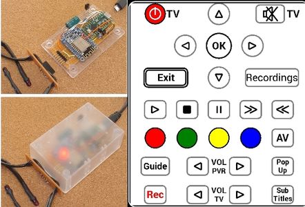
This will get you started using the pfodApp screen display shown above. The next step is to modify the screen display to suit your own unique needs.
Overall code design
The ESP8266 runs as a server and when the pfodApp connects, pfodApp asks for the main menu. The ESP8266 then serves up a menu with two menu items each with a drawing. pfodApp then request the drawings, which are served in a number of parts, and displays them. When the user presses a button, pfodApp send a command to the ESP8266 with the menu item and button commands. The ESP8266 then sends these on to the TeensyLC via the hardware serial connection, e.g. Ah for the TV power button. The TeensyLC then looks up the command 'h' in the 'A' group of commands and sends the associated IR code.
The file cmdDefines.h, links both together and is used in both the ESP8266 and in the TeensyLC. In the ESP8266 it is used to set the button commands and in the TeensyLC it is used in the IR codes data structure.
How the screen buttons work
There are two parts to a pfodApp button, the display and the active area (touchZone and its touchAction). The display is build using the drawing primitives available in pfodApp, see the pfodSpecification.pdf for the details and Custom Arduino Controls for Android for examples. At the bottom of the Wifi_IR_Remote_ESP8266.ino are a number of methods for drawing symbols etc. For example, the draw65square method draws a 6 x 5 button with a label, touch zone (active area) and touch action.
void draw65square(double c, double r, char cmd, char* label) {<br>  dwgs.pushZero(c, r);
  if (label != NULL) {
    dwgs.label().text(label).send();
  }
  dwgs.rectangle().rounded().centered().size(6, 5).color(dwgs.GREY).send();
  dwgs.touchZone().cmd(cmd).centered().size(6, 5).send();
  dwgs.touchAction().cmd(cmd).action(dwgs.rectangle().filled().rounded().centered().size(6, 5).color(dwgs.GREY))
  .send();
  dwgs.popZero();
}
pushZero moves the current zero and scaling (popZero reverts to the previous zero position and scaling) so to draw a button use pushZero to move the current zero to center of the button. Draw the button centered on the current zero and then popZero to undo the pushZero. See Custom Arduino Controls for Android for more details. TouchActions update the screen display as soon as the user touches it to give them visual feedback. In this case the rectangle is just filled in with GREY. When the response comes back from the server (the ESP2866) the touchAction is undone.
How repeat buttons work
When you press a button on your mobile pfodApp sends a command to the ESP8266 containing the command for the button pressed, the command for the menu item the dwg is displayed in as well as the type of button press. For example if you press the TV power button, pfodApp sends {V1:A~h`2`0`0} The V1 is the version number of the dwg, A is the command for the menu item and h is the command for the TV power button. `2`0 are the col and row, in the active area of the button, that was touched. The `0 is the type of touch action, in this case just a TOUCH. Others actions include CLICK, PRESS, DOWN, DRAG and UP When the touch area is defined it includes a filter on what types of touch actions it will respond to.
Non-repeat buttons have a touch type filter of TOUCH, the default if none specified. This means just one command is sent when the active area is touched. Nothing is sent when the user moves or lifts their finger off the screen. In the ESP8266 sketch, the TOUCH sends the button menu cmd and button command to the TeensyLC via the serial connection. E.g. Ah
The active area for a repeat button, e.g. PVR Vol UP, has a touch type filter of DOWN + PRESS + UP and so sends commands for each of those touch actions. In the ESP8266 sketch receivies the DOWN pfodApp command, {V1:A~t`0`0`1} where the 1 on the end indicates this command was generated by the finger DOWN action, and the sketch sends At to the TeensyLC. If the user leaves their finger on the button then after a short time the PRESS action comes into play and sends the pfodApp command {V1:A~t`0`0`16}, where the 16 indicates this command was generated by a PRESS action. The ESP8266 sketch then sends the char > to the TeensyLC telling it to start repeating the last command at the repeat interval specified in its data store. When the user lifts their finger off the screen, pfodApp sends the command {V1:A~t`0`0`4}, where the 4 indicates the UP action. The ESP8266 sketch then sends the char . to the TeensyLC telling it to stop repeating the last command. See the code below.
In the TeenslyLC the macros tvRepeatEntry(X, Y, R) and necRevRepeatEntry(X, Y, R)let you specify the repeat interval, R, in mS.
When the ESP8266 receives the pfodApp command, the pfodParser parses it and returns the menu item command
uint8_t cmd = parser.parse(); // parse incoming data from connection<br>     . . .
      if (cmd != 0) { // have parsed a complete msg { to }
        if ('.' == cmd) {
         . . .
        } else if ('A' == cmd) {
          char dwgCmd = parser.parseDwgCmd(); // parse rest of drawing command, return first char of active cmd
          if (parser.isPress()) {  // send repeat
            Serial.println('>');<br>          } else if (parser.isUp()) {  // send stop repeat
            Serial.println('.');<br>          } else { // TOUCH  and DOWN handled here
            //send button cmd to IR TX
            Serial.print('A');
            Serial.println(dwgCmd);
          }
          // now send response back to pfodApp via WiFi nothing needs to be updated so just send empty response
          parser.print(F("{}"));
Macro commands
There is one macro command it this example code. It is for the TV_POWER button. When recording the TV_POWER signal from the existing remote, it always sent the IR signal 3 times, no matter how short the button was pressed. Also the users wanted the TV to start up Muted. So a special code enum, PANASONIC38_4004_POWER_MACRO_code, was added together with its macro and handling code.
} else if (codeType == PANASONIC38_4004_POWER_MACRO_code) { // TV_POWER and TV_MUTE is hard code here<br>    // PANASONIC address 4004 38kHz
    uint32_t panasonicData = *((uint32_t*)data);
    if (mode == 1) {
      Serial.print("PANASONIC38_4004_POWER_code : 4004"); Serial.println(TV_POWER, HEX);
    }
    // send power code 3 times with 74mS delay between each one
    sendPanasonic38(0x4004, TV_POWER);
    delay(74);
    sendPanasonic38(0x4004, TV_POWER);
    delay(74);
    sendPanasonic38(0x4004, TV_POWER);
    delay(5000); // wait 5sec and then mute
    sendPanasonic38(0x4004, TV_MUTE); // send mute after power (on or off)
  }
Step 7: Extensions
On-screen Popup Help
Although not used in this example, you can easily add on-screen popup help for the user. See Arduino101 Starter (Help_hidable.cpp and Help_hidable.h) project for an example of adding popup help. When the user touches the help button, the popup help appears immediately and remains visible as long as the user keeps their finger on the help button.
Adding Extra Remotes
The example sketch here only has the PVR remote and the useful TV remote buttons. To add other remotes (and all the TV remotes buttons) you can add one or more sub-menus to the main menu which display the controls for another remote. The sub-menus can be opened either by a menu button on the main menu (the pfodDesigner lets you set this up and generates the code for you) OR by a button on one of the dwgs. You could also just add more dwg screens below the existing two menu items.
Conclusion
This Wifi_IR_Remote replaces one or more existing remotes with control from an Android mobile (via Wifi). Any Android mobile, with pfodApp installed, can be used. One pfodApp licence allows multiple family members to use it. You can customize the screen display to group common buttons from different remotes together on the same screen to suit the way you use your devices. You can customize button size, shape, colour and add labels to make the screen easier to use.
The code includes a recording mode (3) to capture the existing remotes IR signals, and there is push button to allow you to setup your network's wifi name and password via a configuration web page without re-programming.
