

Introduction: DIY 3S1P LiPo Battery Pack


Today, I'll be putting together 3 lithium polymer battery cells to make a 3S1P (3 series 1 parallel) battery pack that can be used with RC equipment and I'll be using it to power my flying rectangle project. While you can buy your own lipo battery packs easily, it's not always that you can find what you exactly want because of space and weight limitations or that you need high capacity with low cost and you don't always need the high discharge rates which can get very expensive but is sometimes the only option for high capacity batteries. Plus where's the fun in buying when you can make your very own hand made pack.
Caution: This project involves the use and modification of lithium polymer batteries which are extremely sensitive to heat and has the potential to burst into flames of highly toxic fumes. Be sure to work in a well ventilated area and have a dry powder multi-purpose fire extinguisher near by. Never try to put out an electrical fire with water, it will make things worse. I'm not responsible for any damage or harm done to property and/or humans and animals.
Step 1: Tools and Building Materials


For the tools you need:
- A soldering iron (30W is sufficient)
- Solder
- Side cutter
- Plier
- Wire stripper
- Box cutter or utility knife
- Kapton tape
- Heatshrink tubing (5mm and 50mm (optional if you want to cover the pack))
- Lighter or heatgun
- Balance charger/lipo charger (board shown in second photo) (optional)
For the building materials you need:
- LiPo battery cells
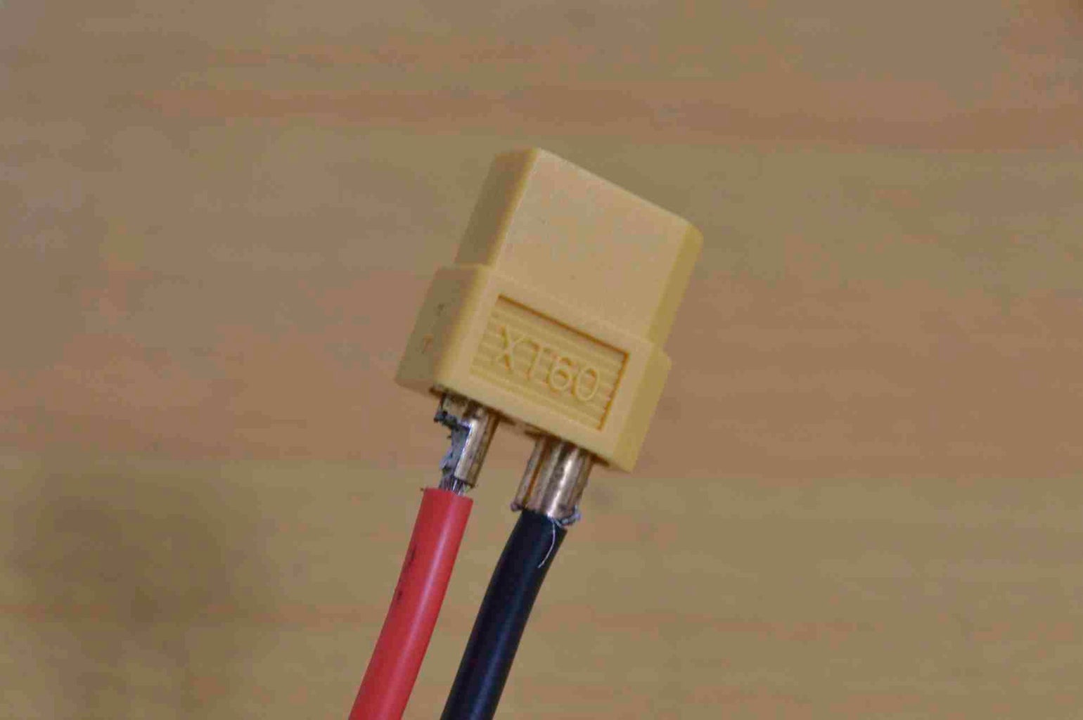
- Female XT60 connector or the red T-type connector
- Silicone rubber or other high temperature 16 AWG - 12 AWG (red and black) 15cm each color
- Balance cable, I used a data cable that had the balancing connector on it
Step 2: Let's Get Building! the Cells


I chose 4000 mAh 8C cells as I plan on using it with a BLDC motor that draws 15A. The maximum current a battery can supply is its C rating multiplied by its capacity, that makes my battery capable of delivering 8*4000/1000 = 32Amps putting my 15A motor within a safe limit.
I decided to charge each cell individually with the usb charger board shown in step 1 so it's balanced once assembled and won't give the balance charger a hard time.
First we remove the protective tape at the top of the battery to reveal the discharge tabs. Under the tape, you may or may not find a protection circuit. We can begin to desolder the discharge tabs from the wires or the protection circuit if present. You'll need to do this for all cells. You should do this as fast as possible to avoid damaging the battery and reducing its capacity with the soldering iron's heat.
Step 3: Cell Arrangement and Soldering


I'm going for a 3S1P configuration, so I arrange the cells so they alternate orientation each cell so the positive terminal of on cell touches the negative of another. Make sure you DO NOT short circuit to cells together by connecting them + cell1 to - cell2 and - cell1 to +cell2. Unfold the tabs to be able to solder the cells together.
Once you're okay with the arrangement, tape the cells together to help you solder. Solder the tabs together, again quickly to avoid damage and capacity loss.
Step 4: Wiring Preparation


Measure the balancing cable from the far tab of the battery, along the side you want the wires coming out until just before the end of the battery by 2 cm and cut. Do the same for the discharge leads but this time make room for the XT60 connector length (which I forgot to do) and have it end by the battery's end.
Split the balancing cable and cut each individual wire reach the tabs without having slack. The wiring order is according to the provided schematic. Strip a small length of each wire and tin it.
Strip the silicone rubber wires with the utility knife by rolling it on a flat surface under the cutting edge. Tin both its ends and solder them to the XT-60 connector keeping the correct polarity in mind. Apply the heat shrink tubing to the XT60 side.
Step 5: Solder All

Solder all the wires to the battery cells as shown in the schematic. Still be quick on the balancing cable, don't worry as much though about the discharge leads as the wires themselves will suck some of the heat but still don't be too slow. I'm sorry I don't have a photo for soldering the wires, it's almost impossible to take a decent photo with a soldering iron in one hand and a 2 lb DSLR camera in another.
Step 6: Time to Test


Wrap the cables as well as the cells with tape to provide some stress relief for the tabs. I opted for covering all the solder joints with kapton tape to avoid short circuits and I admit it, for the looks too.
Measure each cell at the balance plug and you should find that all cells are within +/- 0.1 volt of each other. Measure the voltage at the output terminals and it should add up, number of cells x3.7v/cell, 3*3.7 = 11.1v. Mine measures 12.1v as they are almost fully charged to 4.03v each.
If all went good, this is the best time to wrap the whole battery in large heat shrink, an update on that soon.
Step 7: Done!

Aaaaand you're done! Making this instructable was as awesome as the battery pack itself. Thank you for reading till the end. Stay tuned for the large heat shrink update and the flying rectangle instructable (a project originally by the great YouTuber Samm Sheperd, check out his awesome channel on airborne RC projects.) Let me know how it went for you and what you did with it.


