

Introduction: DIY Anemometer With Hall-Sensor


I wanted to build a vertical wind generator, but first I need to check if there is enough wind for my project.
I know, I could buy a "ready to use anemometer", but where is then the fun.
So I decided to build my own.
Link to the video Anemometer on youtube
Step 1: Idea and Design


I designed my idea in Sketchup 8. The 2D cad is done in Qcad.
All turns out pretty good
Step 2: The Middle Part With the Ball-Bearing


The parts have been made with a laser cutter with 3 mm acrylic glass. A ball bearing (22mm x 7mm x 8mm) fits exactly in the middle of the parts. I used 3 little neodymium magnets (5mm x 2,5mm) and placed them in the hole witch was designed for them. The 8mm thread is fixed with two 8mm nuts.
Step 3: The Rods and the Wind-Shovels


Three PVC U-profiles with a length of 17cm are used as rods. Three 80mm half plastic balls from a hobby shop are used as wind-shovels. I removed the small little part from the plastic balls and a 3mm hole is drilled in the middle. They are then fixed on the rods
Step 4: Bearing Protection


A half plastic ball with the size of 50mm is used as cover, to protect the ball bearing.
Step 5: The Hall-Sensor


I removed the little pin strip header from the hall-sensor, and replaced it with 3 wires. Blue 3mm laser cut parts are used as housing for the sensor, but blue was not a good idea, so I replaced the two upper parts with transparent acrylic, so I can see the Led thru the holder.
Step 6: The Finished Installation


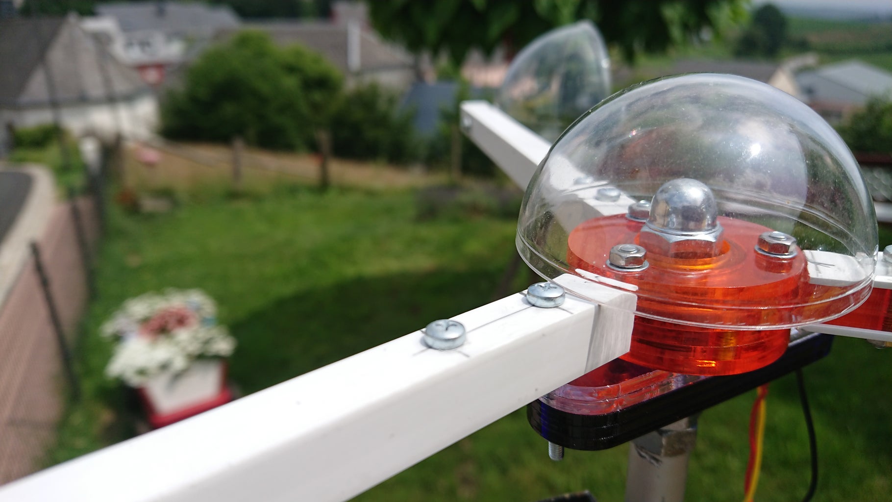


I used an old aluminum rod to fix the Anemometer at the outside. A wire is then connected to the build and so I can receive the impulse from the hall-sensor in my workshop. I just connected a Led to it, and it works.
The next step will be to connect it to an Arduino to measure the impulse length and to calculate the wind speed.


