

Introduction: DIY Aquarium Controller


Hi! In this instructable, I wanted to show you how to make the aquarium controller. There are many controllers available on the Internet, but they cost at least $100. My controller cost about $15. Another great thing about making your own aquarium controller is that you can personalize it.
Alright, but why do I need it?
Aquarium controller is a huge help for every aquarium owner. It can control LEDs (turn it slowly on and off at a given time), measure the water temperature (and turn on the alarm if the temperature is too low or too high), feed your fish, monitor the water level, check the pH of water, etc. It can control everything that you have to control in your aquarium and measure every parameter that is relevant to you, your fish and plants.
OK, you know why you need it, now let's see how to make it.
NOTE: This instructable is only about making the aquarium controller, not about making the aquarium itself. I assume that you already have a "working" aquarium with fish and plants or you want to make a new aquarium.
Step 1: What You Need


First, you need an aquarium and a hood for it (you can make the hood by yourself. More information in step 2).
Electronic parts:
- an Arduino (I used Nano 3.0) - you can use any Arduino but it should have at least 30 kB of memory
- LED strips (more about LEDs in step 2)
- waterproof temperature sensor (I used DS18B20) - I used 2 sensors, but one is enough
- LCD display (I used 1602 I2C)
- real-time clock (I used DS3231)
- 4 channel digital touch sensor (I used this one)
- water level sensor (not used)
- transistor to control LEDs (I used IRF840, but you can use any other MOSFET)
- 5V voltage regulator
- buzzer (optional for alarm)
- 10k, 4.7k and 1k ohm resistors
- DC power supply jack female socket 5.5*2.1 mm
- DC power supply 12V (depending on how much power consumes your led strips choose the power supply with enough power)
Other parts:
- universal PCB board
- some male pin headers
- a lot of wires (female-to-male, female-to-female and solid core wires)
- a lot of solder
- zip ties
- heat-shrink tubes
- hot glue sticks
- wire connectors
Tools:
- soldering iron
- wire cutter
- heat gun
- hot glue gun
- scissors
- 3D printer (to print mount for LCD)
- tape measure
- driller (optional)
- screwdriver
Skills:
- Arduino programming (check out this class)
- soldering (check out this tutorial)
- 3D printing and 3D drawing (check out this class)
As I said earlier all the parts (except LED strips) cost me about $15.
Step 2: Light

I'm not an expert so there are some links which explains everything about the light:
- all about light source in an aquarium
- about the light spectrum
- using LED as the light source in an aquarium
- LED buyers guide
OK, if you read the articles above, you know enough to choose the type of lighting for your aquarium. In this instructable, I will use LEDs, because they are easy to control, more durable than other types of lighting and they consume less power. Now you have to answer some questions.
Waterproof or not?
Generally, it's better to use non-waterproof LEDs. High humidity in an aquarium can damage even waterproof LEDs, so if you'll make a hood for the LEDs and isolate them well that no water will come to the LEDs, your lighting system will work for a long time. I didn't do this. I chose waterproof LEDs, I glued it to the hood and after a month I had to fix one panel because some LEDs burned, also LED strips peeled off from the hood and fall into the water. Hopefully, nothing bad happened. So if you want to keep LEDs and fish safe you have to make or buy a hood that has a transparent bottom and no water can get through it (like this one).
RGB, strips of different color or one color strips?
RGB is fantastic because you can control the light color, but it's more expensive and harder to control than just one color LEDs. Do you really want to change colors? If you want to, for example, imitate the moonlight, the RGB lighting is required, but if you don't, you can choose different color strips or one color strips. If you choose one color strips the best are LEDs with a color temperature from 5500 K to 6500 K - it's the same light color that sun emits. It contains a full light spectrum from red to violet, so your plants will have the right light for photosynthesis and the fish will look great.
Many LEDs that emit less light or few very powerful LEDs?
It doesn't really matter. In my opinion, many LEDs that emit less light are better because they look like there is one big light source. But it's just my opinion.
Step 3: Aquarium Controller Board


Now let's make the board which will control the aquarium.
LEDs power
You have to make connectors to which you can easily connect the LED strips. To do this you need pins and 2 wire connector like on 3rd image. Screw longer part of the pin to each connector. Make as many connectors as you need to connect your LED strips. I needed 3 - one for each strip.
Soldering parts
Plan where you will solder the parts (you can look at image 4). I use a buzzer to alarm when the temperature drops too low or rise too high, but you don't have to use it. Remember, that 10k ohm resistor is between GND and Arduino PWM port which control the MOSFET, 1k ohm resistor is between the Arduino PWM port which controls the MOSFET and MOSFET gate and 4.7k ohm resistor is between the Arduino port which reads the temperature from sensors and +5V. Try to put pins as close as possible to the proper Arduino ports.
Now you can solder the parts to the PCB board. If you soldered all parts to the board, you can wire them. Remember, - from LEDs to source in MOSFET and drain from MOSFET to GND. And also remember to connect LEDs directly to 12V from DC power supply, not to the voltage regulator. You can add labels to pins to know which pin is which.
I didn't use the water level sensor, but if you want, you can use it.
Arduino program
Connect the board to the power supply. If the diode on Arduino turned on means that there are no short circuits. Now you can upload the program. To run this program you'll need a few libraries:.
- LiquidCrystal_I2C
- DS3231
- OneWire
- DallasTemperature
- Wire (standard library)
- EEPROM (standard library)
If you downloaded all libraries you can upload the program to the Arduino. You'll find the code at the bottom of this site (or you can download it here ).

Step 4: Mounting All the Stuff


LED strips
First, you have to know how many and how long strips you need. If you use a hood not designed for LEDs (as my) check where you can attach the strips.
Cut the strips and solder wires to + and - on the strip. If the LEDs won't have any cover you have to isolate the wires. Use heat shrink tube and insulating tape, and a lot of hot glue. Now attach the LED strips to the hood. You can use acetone to degrease the surface, also use a lot of hot glue to attach the strips to the hood that they won't fall down. If the strips are attached, run the wires to the place where the control board will be.
Test
Now it's time for the test. Connect the display, RTC, 4 channel digital touch sensor, temperature sensors, water level sensor (if you have one), the LEDs and connect the power.
If everything is turning on and LCD displays the time and temperature everything works great.
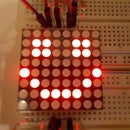
Now I'll tell you how to control it. Functions of each button: 1 (look at 5th image) - menu, ok, accept; 2 - cancel, back; 3 - down, left; 4 - up, right.
To change the time you have to click 1, then 2 times 4 and 1 (to enter the Clock). Click 1 to set a time. By clicking 3 and 4 choose hour, then click 1 to accept hour, then choose minute and click 1, then choose seconds. The changes will be saved when you click 1 after choosing seconds. If you made a mistake and you want to cancel click 2.
Then move to Set Date and set the date as you set the time. Next set if the summer time is on or off (default is off). Lastly, set the day of the week.
Now you have to set when you want the light to turn on and off. So click 2 to go back to the main menu. Click 3 two times. Click 1 to go to Light settings. If you want to completely turn off lights go to Mode and set from Auto to Off. But now you have to test the LEDs, so don't do that. Click Dawn Start to set when you want to turn the lights on. Then set the dawn duration (how long should the LEDs turn on). Click Dusk Start to set when you want to turn the lights off. And after that set the dusk duration (how long should the LEDs turn off). If the time is between the Dawn Start and Dusk Start the LEDs should slowly turn on, if not, change the Dusk Start that it'll start later. If the LEDs are turning on everything is great. If you will disconnect the power all settings will be saved in EEPROM.
Now you can mount the LCD to the aquarium hood.
LCD handle
First of all, download and print the STL parts which you will find at the bottom of the site (you can download them here). You'll need 6 electronic spikes and 6 mount spikes.
Attach the 4 channel digital touch sensor to the touch panel cover using 2 electronic spikes. Then fasten the touch panel cover with 4 channel digital touch sensor to the mount LCD using 2 mount spikes (image 5).
Connect the wires to the touch sensor and bend the pins that they won't prevent fastening the LCD. Now fasten LCD with 4 electronic spikes, connect the wires to the LCD (image 8) and attach the LCD cover to the mount LCD using 4 mount spikes. Voilà, you've made the LCD handle.
Attach LCD to the hood and wire the rest
Using zip ties, tie wires from LCD and touch sensor together. Using hot glue, attach the LCD handle to the aquarium hood. Place the controller board in its place and connect everything to it. Connect the power supply and check if everything works.
Attachments
Step 5: The End

This is it. You've got a working aquarium controller. Check carefully the menu. There are some options which might be helpful for you. This is just a prototype. You can expand it - add more sensors, more things to control. But if you want to add these things you have to add the SD card reader to the Arduino, because you will run out of memory.
So upgrade it and share photos. Hope that you liked this.
Thanks for reading through and see you soon.
Simonexc
Step 6: Troubleshooting
Error:
\LiquidCrystal_I2C\I2CIO.cpp:35:26: fatal error: ../Wire/Wire.h: No such file or directory
Solution:
In LiquidCrystal_I2C library in file I2CIO.cpp change 35th line from #include<../Wire/Wire.h> to #include<Wire.h>
Error:
There is no text on the display or there are strange symbols.
Solution:
Wires aren't connected properly. Wiggle the wires a little bit or solder them.

Participated in the
Make it Glow Contest 2016

Participated in the
Design Now: 3D Design Contest 2016

Participated in the
Arduino Contest 2016


