

Introduction: DIY Arduino Robotic Arm


Hello Guys and Gals,
Welcome to another project by me, this time we will focus on creating a cheap and simple robotic arm that is controlled by an arduino and 3 potentiometers. This simple device only requires 5 volts of power to be able to operate. The build time is about an hour or so. Expect to be really patient while making this because all the components have to move in unison or you will have a problem.
This Robotic Arm is a really easy and simple project for most new Hobbyist! I decided to make my own robotic arm when I realized that I had some left over servos from an old project. I looked on instructables for an easy set up in which you did not have to buy a kit, but unfortunately I did not find any. All projects either required a CNC machine or a kit, so I decided to just make my own version that used Popsicle sticks as the frame and micro servos to move around. The Claw as well was homemade because I could not find any affordable deals. This is simple prototype, and version 2 will hopefully be bluetooth powered or controlled by phone/pc. Then I hope to create a better frame and also switch out the servos for better ones.
Also please take a second to subscribe to my new Youtube Channel. Thank You!
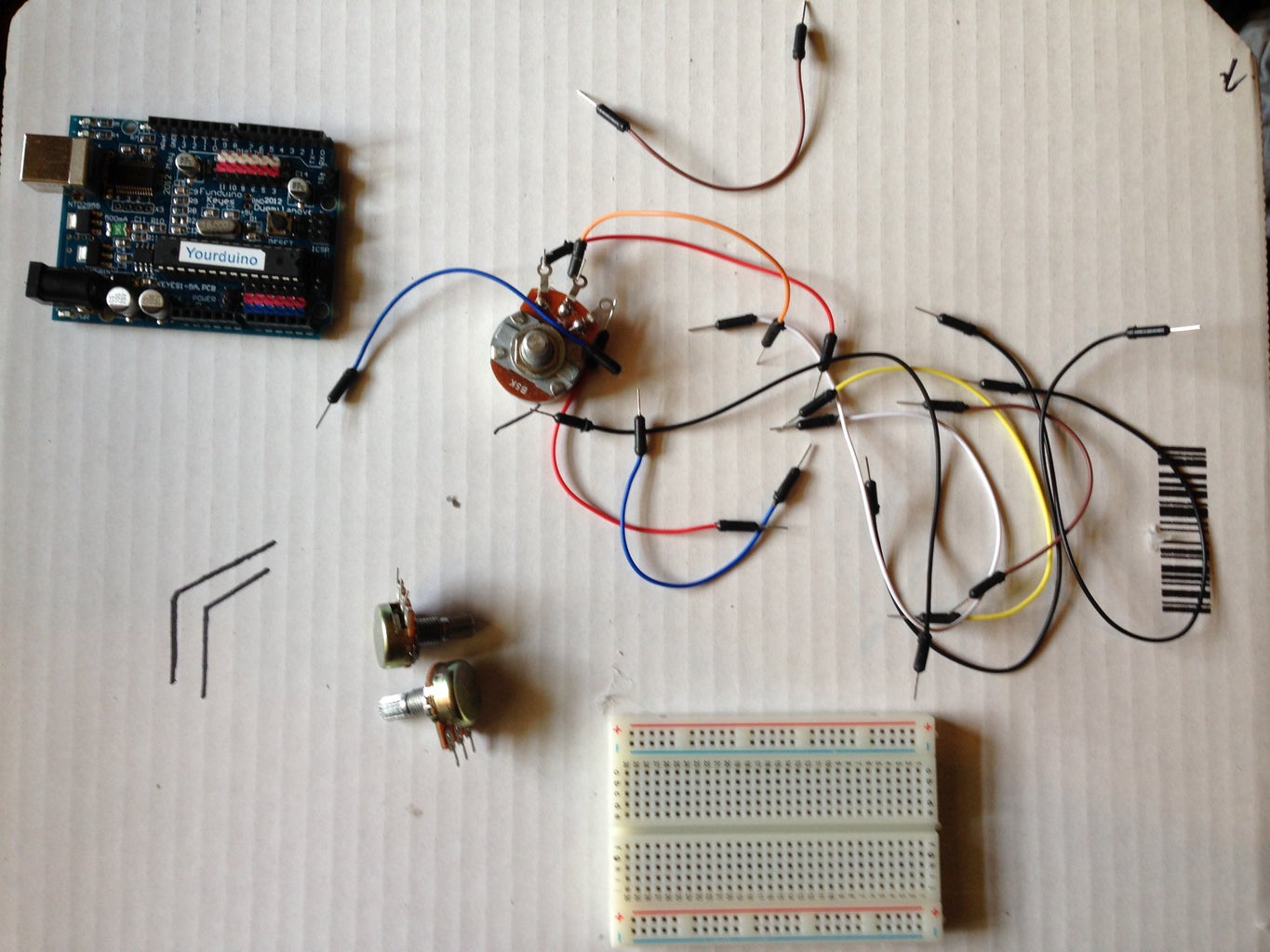
Step 1: Materials Required


The tools and materials are very cheap for this project, and it should not run you more than $20 USD dollars. If you have some servos lying around then you are lucky. I should also point out that if you have a more powerful servo you could use 3 instead of 4 unlike me. These are where I got my parts please check out other sites for deals before you make a purchase.
-Popsicle Sticks $3.65 [If you want you can substitute a better suited material]
-Micro Servos x6 $16 [Please try to look for deals]
-Potentiometer x3 $2.74 [Again you make have some of these laying around]
-Jumper wires or just regular wires
-Yourduino or Arduino with a motor shield.
- I used an Yourduino because it came with many ports that allowed for you to plug in multiple servos at once. I keep the limit to about 4 to not burn out the board.
- If you use a regular Arduino then you will need a motor shield that allows support for 4 motors.
-Glue Gun, Hammer + Nails, base to hold arm and enclosure for the controller
*Optional is also a pcb if you want to make your controller circuit more sturdy and less complex.
Step 2: Step 2: Assemble the Base and Forearms


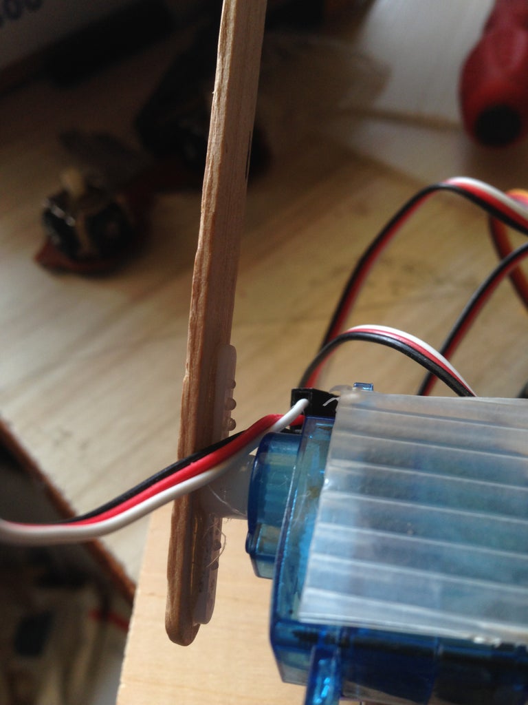


Okay find a plank of wood or material that would be able to support the weight of the entire arm structure. Once you found your material I found that it is best to glue down the servo and then nail in the brackets into the wood so that it can have even more support and weight distribution. Doing something as small as this will make your micro servo 2x as strong [I didn't do the math]. Then Hot glue the next two servos together on top of the base servo. Make sure that they are facing opposite directions but parallel and test that the servos would be moving together in parallel. Hot glue a piece of material that could hold down the servo.
Next you have to lay out the frame required for the structure of the arm, and then hot glue the gear of the servo to Popsicle stick that it will be controlling. I made my frame have a wide outlook because I did not have enough motors to add elbow support. So by setting up like this I create a larger range for the arm.
Make sure that the connections for the shoulder servos are glued correctly and that one is not further or behind the other. And finally add the next horizontal frame support to make sure that motors are moving together when in use.
Step 3: Step 3: Assembling the Claw


First we have to glue the top servo motor and with it the horizontal frame needed to hold it in place. Make sure that the bonds are strong you would hate for you robot to come apart mid testing. Also at this time make sure to add a special gear that has only one end. This is what we will use to control the claw.
The Claw
The claw I have was found from a toy construction kit. I don't even think that it was suppose to be a claw. You can choose to buy your own robotic claw or you can look around for household items and use your creativity to make one. That is exactly what I did. Maybe you don't want a claw, maybe you want a robot that gives you a high five, fist bump, or just holds a platform so you can place materials on it. It could even be a helping hand for soldering.
Step 4: Step 4: Time to Wire Everything Up


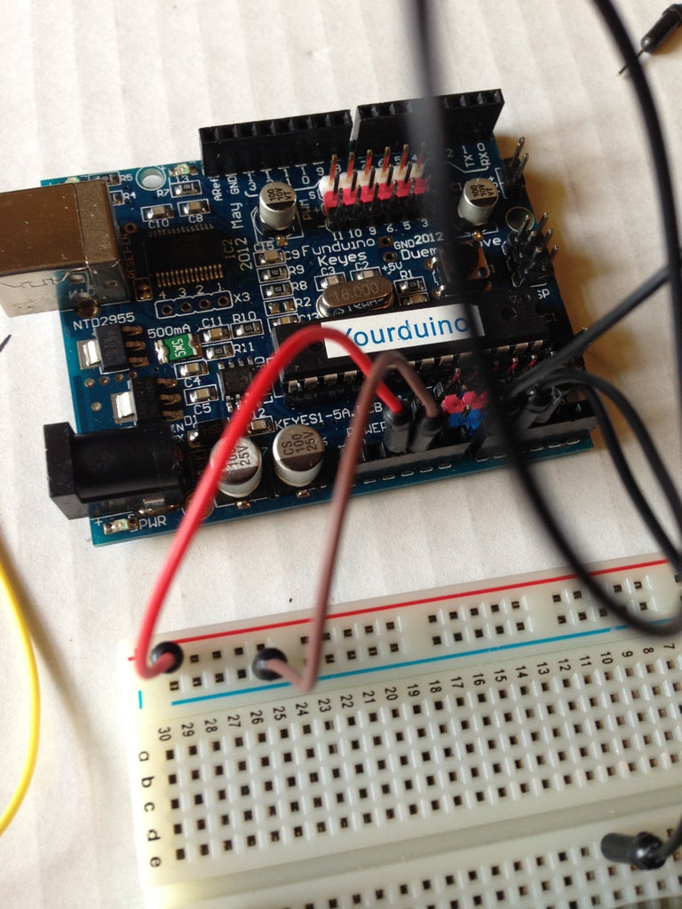


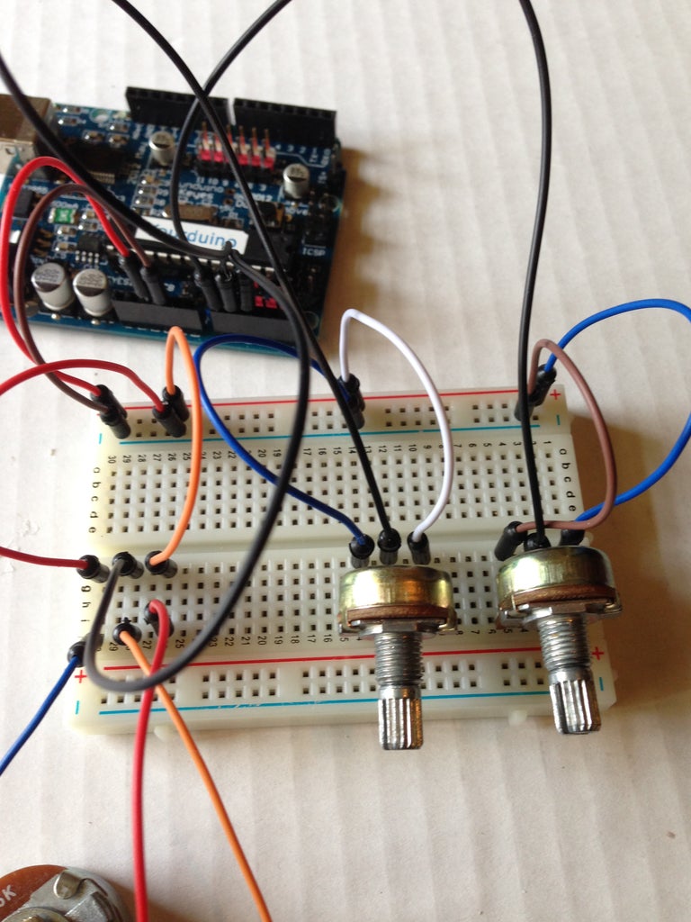
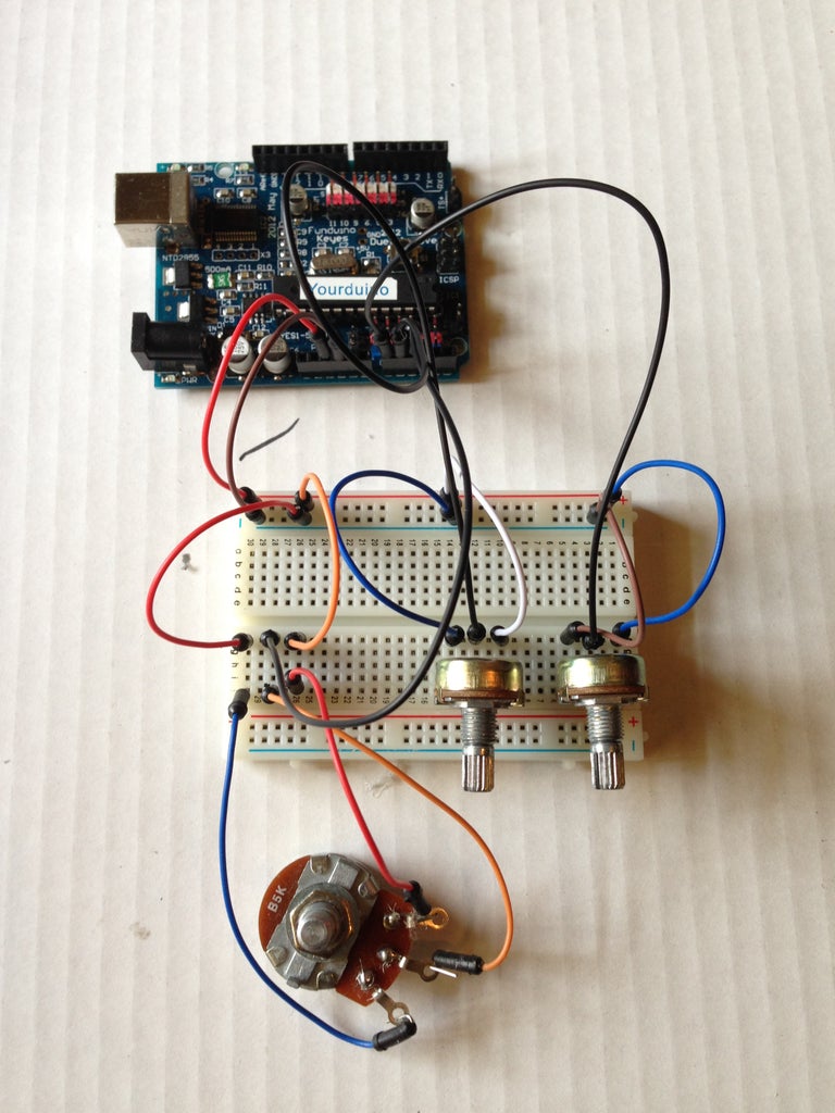


Okay so now we will be creating the controller that will allow for the robotic arm to move around and do stuff. Cool stuff I might add. The first image image shows the wiring of the potentiometer and, it is very important that you take care in following this format. What I did was just plug the 5 volts and gnd from the breadboard directly into the terminals of the breadboard because clearly 3 potentiometer pins can't fit in one 5 volt hole.
- First we start of by plugging in the potentiometers[Pots] into their rightful terminals.
- Connect the middle of each Pot into A0, A1, A2 going from right to left.
- Connect the GND and the 5 volt from the Arduino into the breadboard and then connect the pots gnd into the gnd row.
- Connect the positive end of the pots which is the right one into the 5 volt row.
- Finally plug in the servos.
- The base goes to 3
- The left shoulder goes to 5
- The right shoulder goes to 6
- The claw goes to 11
- That should be it, test your servos one more time to make sure everything is working
Step 5: Step 5: the Code

Okay so the code is attached and posted below. The first half of the code identifies the various materials required to control the arm. The bottom half of the code tells the arduino what to do when you turn the pots to a certain direction. I should also point out that I was able to trick the code into allowing two servos run at the same time instead of one at a time. This allows for the shoulders to move together.
<p>/*<br>  Arduino Robotic Arm
  by Amidou Kante; Torigac

  July 14th, 2014

  Simple robotic arm that is controlled by three pots.
*/
#include <servo.h>
Servo base; // Tells the arduino what servos we are going to
Servo left; // use. I name them by they function or location.
Servo right;
Servo claw;
int potpin = 0; //Tells the arduino the locations of the pots
int potpin2 = 1;
int potpin3 = 2;
int val;  //Tells the arduino what variable to use to store
int val2; // the position when turned.
int val3;
void setup()
{
base.attach(3);
left.attach(5);  //Tells the arduino where the servos are plugged
right.attach(6);  // in.
claw.attach(11);
}
void loop(){
  {
    val = analogRead(potpin);  //tells arduino which pot controlls
    val = map(val, 0, 1023, 0, 179); //current servo, and then maps
    base.write(val);    //the dial the pot is on to move the servo
    delay(15);      //waits for the servo to move
  }{
    val2 = analogRead(potpin2);
    val2 = map(val2, 0, 1023, 0, 179);
    left.write(val2);
    delay(15);
  {
    val2 = analogRead(potpin2);
    val2 = map(val2, 0, 1023, 0, 179);
    right.write(val2);
    delay(15);
  }
    {
    val3 = analogRead(potpin3);
    val3 = map(val3, 0, 1023, 0, 179);
    claw.write(val3);
    delay(15);
  }
  }
}</servo.h></p>
Attachments

Step 6: Step 6: Video Demo and End Notes
Okay so thats it guys. Once again this was a prototype project and was a working demo to show the full potential that this product could have. I have included a video demo and also I would really appreciated if you guys took the time to subscribe to my youtube channel it will have many new videos and weekend projects coming up soon. My Channel
I plan on eventually creating a 3d model of this robotic arm and expanding on the claw and the motors so that it can actually be a fully functional robotic arm.
Step 7: TroubleShooting

All I hear is buzzing!
Quickly unplug the motors or the power source. This means that the load is too strong for the motor or that the motor has gotten stuck in the current position that it is in. Use your hand to gently try to turn the motor in any direction.
It Keeps Falling!
Then either the upper level is too heavy or the bottom part of the arm is not reinforced enough.
If you have any more questions then feel free to ask in the comments section.
