

Introduction: DIY Intelligent Autonomus Robot (Electronic Pet) /w Arduino


I love every kind of robots especially the autonomus or intelligent robots, that have a bit more intelligence than avoiding an obstacle. So I decided that I'll build my own inexpensive intelligent robot that has a build in camera, distance sensors, light sensor, sound sensor, lights, solar charger, battery level sensor, IR sensor and arms (that can hold or push anything) and with the help of these sensors and the software this robot became highly intelligent. This four wheel drived robot behaves like a real pet. :) With its solar panel can charge up the build in batteries at any time, when is discharged, then moves away automatically to explore the world with its FPV camera. Well isn't as smart like a cat, it's more similar to a MARS rover, but can react to sounds and with his arms and sensors can deliver anything automatically. Yes, can deliver tiramisu...
Don't worry if you are a beginner in Arduino, I am going to explain everything in this Instructable, and isn't so hard to build.
This is only the first version, with a GPS module I'm planning to add a "follow me" function. My smartphone will send the GPS data to the robot, that compares to its GPS data, then moves to my cellphone. I really hope that I'll be able to add this feature in a few weeks.
Step 1: Tools and Parts


All parts are from the Gearbest.com because they ship parts fast together (not like eBay), and they have low prices (not like Amazon). The full cost is a bit less than 150 bucks. Not every part has a picture above so please click on the link or Google it to view them.
Tools:
- soldering iron
- solder
- wire stripper
- wire cutter
- a PC for programming
Parts:
- Chassis
- Solar PanelArduino UNO (or Mega or LinkIt ONE, we sometimes need more memory)
- Sound Sensor
- Light Sensor
- 14.7k resistor
- 10k resistor
- 1k resistor
- High Power White LEDHigh Power White LED
- Mini FPV Camera
- 4x 18650 Li-Ion Batteries
- 2x Li-Ion Battery Holder
- 2x Ultrasonic Sensors
- Plastic Pieces (for arms)
- 4x Servo Motors (if you don't want to build in camera motion feature only two are enough)
- a lot of Jumper Wires
- a small piece of PCB
- Voltage Step-Up Converter
- Motor Driver
Software:
- Arduino IDE
- Ultrasonic Library
- Servo Library
The software may seem a bit difficult, but it is not impossible to understand, how it works and how the analyzing happens inside a smalll microcontroller.
Step 2: Assemble the Chassis


If you buy the from the same like me, then you'll have a building instructions for the chassis, but this not needed, because it's very easy to build. First of all peel off the safety paper from every single plastic piece then use a screwdriver and mount the motors on the bottom of chassis. Solder a few wires (included with the kit) to the four motors. It's recommended to buy a motor driver, like mine, but you can build one with some research. Mount this on the back of the robot then use the screw terminals to add all of the motors, just like on the pictures above.
Step 3: The Arduino UNO
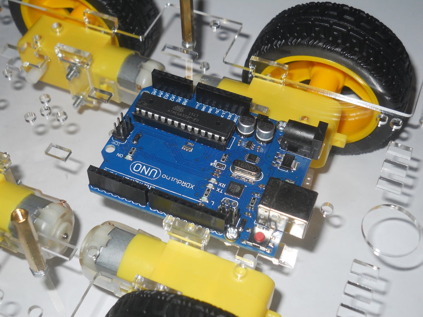


Now that the project is done I see that would be better to use az Arduino Mega, but works also with the UNO, the only problem is that I should use a second microcontroller for the 2. version of the project. I placed my UNO on the center of the case and plugged in four wires in the following digital pins: 4, 5, 6, 7 then connected them to the signal inputs of the motor driver.
Step 4: Mini Multisensor Module


This sensor module has a very important role in the robot. This measures the battery's voltage than gives a feedback to the Arduino, and also measures the light. If senses sunlight charges up its batteries. With some header pins (male and female) I made a voltage distributor and a servo motor driver. With a resistor based voltage divider made a variable 5 volt signal for the Arduino to check the battery's voltage. There is a small seven segment display, that monitors the battery's voltage for the user. (I'll load up the schematic asap). I placed this module next to the UNO with some double sided tape. Connect the light sensor's pinout to the A0 and the battery's signal to the A1.
Step 5: The Automatic Arm / Hand


The easiest solution for making a hand was to buy two servo motors then with some plastic rods make an arm-style holder. This can grab something (example a soda) depending on the distance sensors and release, when he reched its goal, or senses something else.
Step 6: Solar Panel and Charger

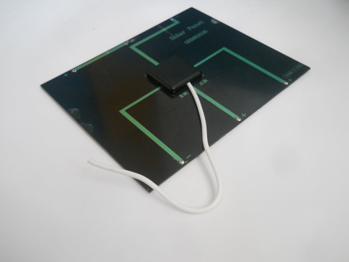
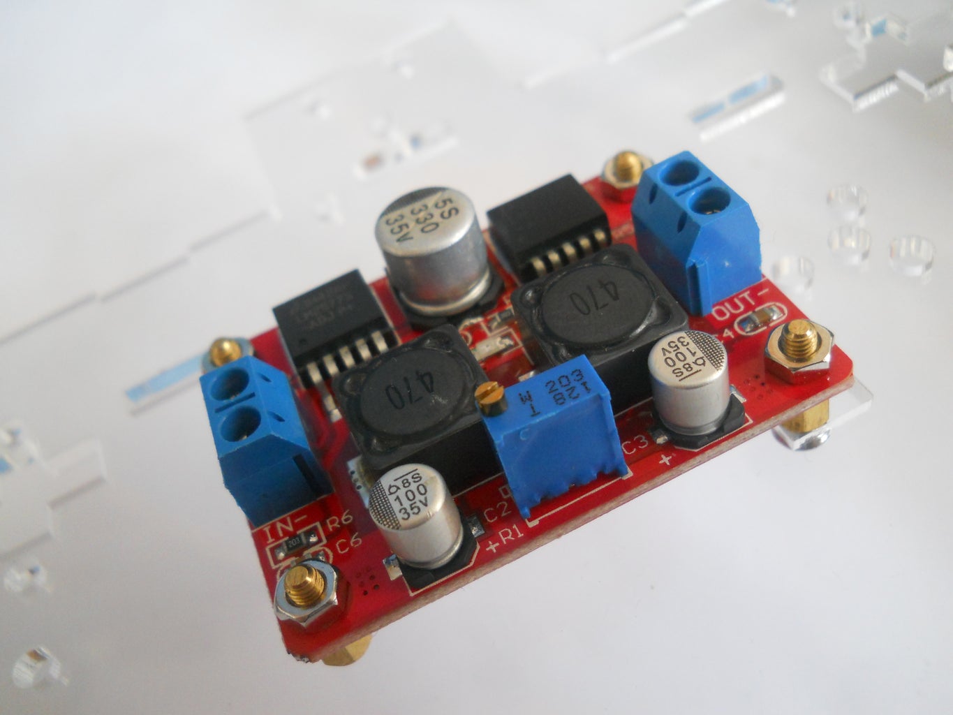


This solar panel can generate enough power to charge up the batteries, but its 6 volts is too low. So I bought a voltage step-up module, that increases the voltage to 9 volts on 0.5A. This power charges up the battery pack in about 6 hours that is relatively fast. Before connecting the battery calibrate the step up module to 9 volts.
Step 7: The Batteries


Please be careful while working with Li-Ion batteries, they have very high current, do not short them. Plug them inthe battery holder and with some extra strong double sided tape mount them on the top of the car. After this cut the end of the rear battery pack and solder a diode to positive ending, this blocks the current flowing back to the solar panel. Connect this to the step up module then take two wires and solder in paralell with the other battery pack, somehow like on the pictures. After this use again some double sided tape and install the solar panels on the top of the robot. (Well I actually did this, but I had to take apart, to add other sensors.)
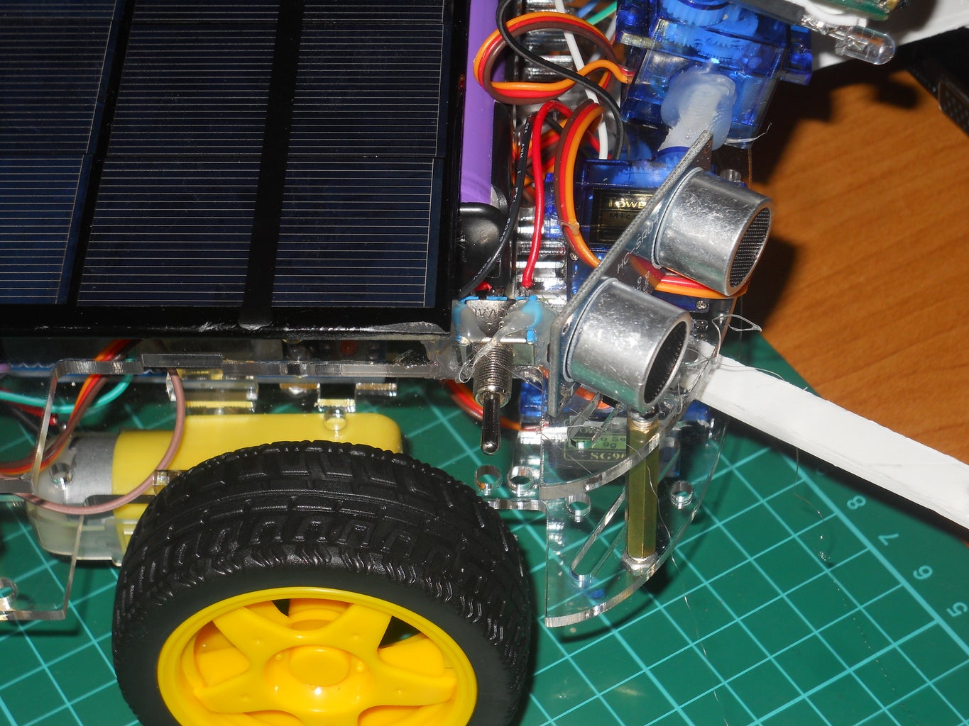
Step 8: Ultrasonic Sensors
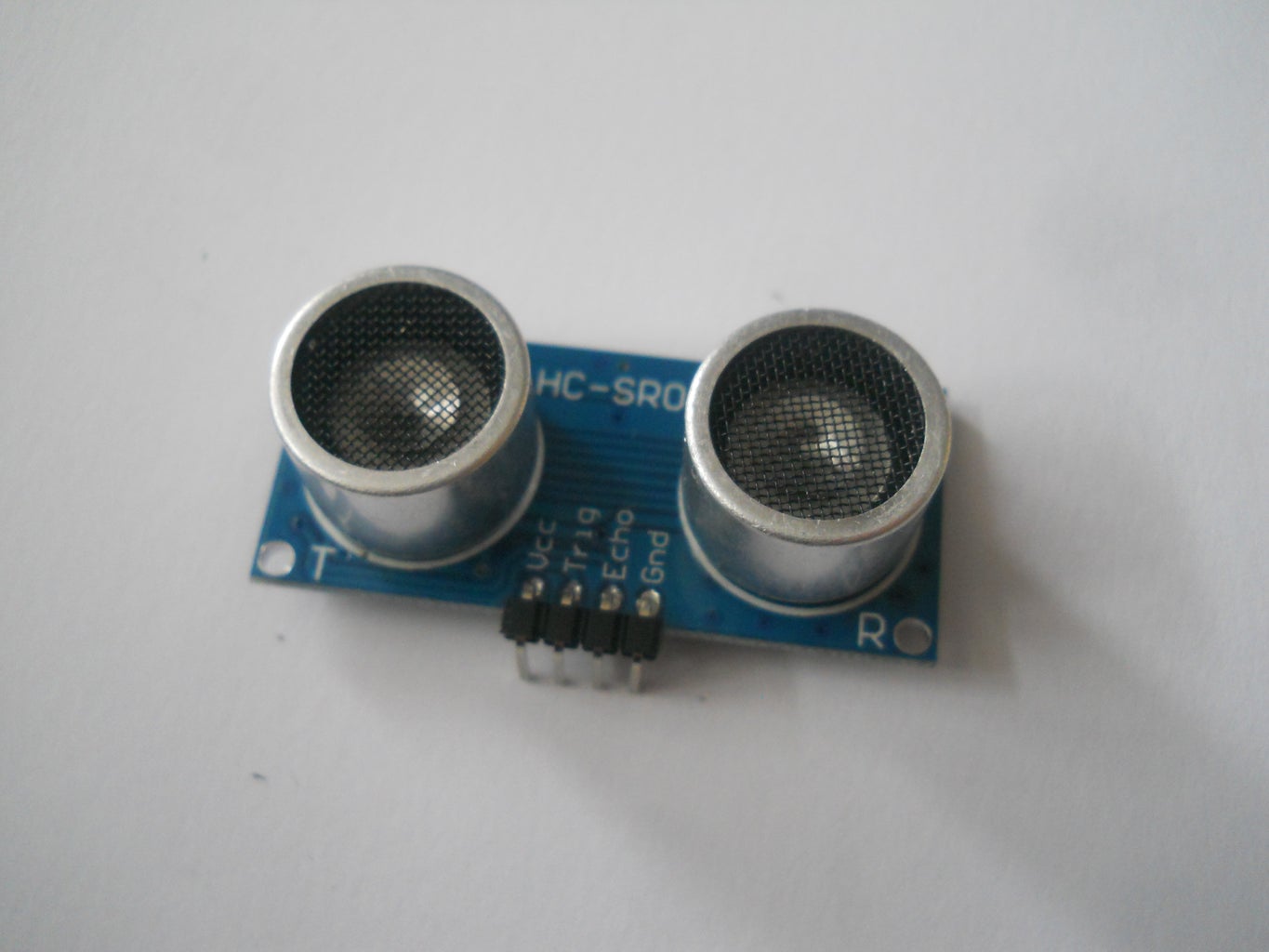


The ultrasonic sensors detects distance between an obstacle and the robot. The signal pins are connected to the following digital outlets: 13, 12, 11, 10. Of course you should power up them with 5 volts, then with some hot glue fix them on the front of the car.
Step 9: Sound Sensor

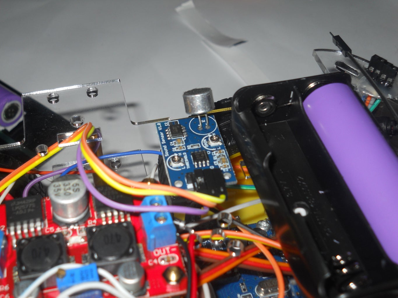
Power up a sound sensor and mount it under the solar panel, like me and connect its signal cable to the A3.
Step 10: The Camera
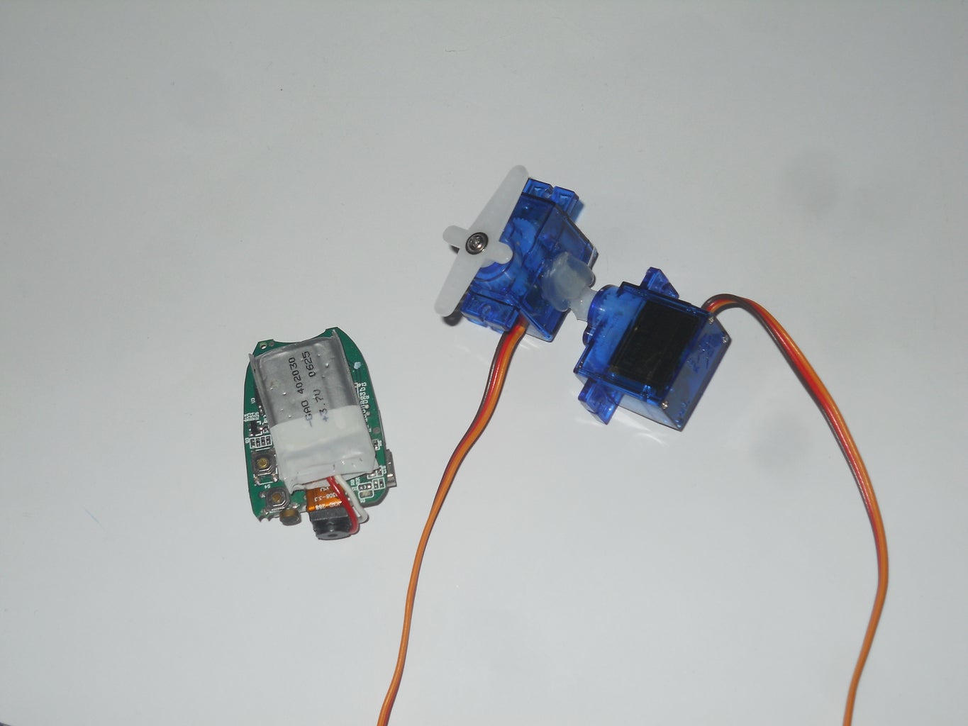

This is a hacked FPV camera that was designed for drones, but I used now for this robot. It's optional to make a servo motor based camera mount that ensures wide angle view. This camera follows the car's direction or when detects sound reacts to it. With RC Ufo app you can view its real time video transmission.
Step 11: Software
This is only the first test code. Download this and upload to your Arduino UNO to test the hardwere. Please be patient I will uptade the software part with the actual code.
Attachments

Step 12: Testing...


The first test went very well, as soon as will be done I'll publish the second GPS version in a few days with schematics. I enter with this project to the Robotics Contest, if you liked, please give a kindly Vote! :D Thank you for watching and hope you enjoyed this Instructable!
Step 13: Version 2.0
As I said there will be many changes:
- GPS
- smarter robot
- follow me function
- better AI (artificial intelligence)

Participated in the
Robotics Contest 2016

Participated in the
Make it Move Contest 2016

Participated in the
Sensors Contest 2016


