

Introduction: DIY Power Bank


Hello again!
I know it's not a new project round here but I decided to make and post a low cost, nice esthetics and practical 5100 m Ah power bank from old 18650 laptop battery pack.
Dimensions of this power bank are 95x50x 24mm.
Hope to like it :)
Step 1: Materials and Tools


PARTS:
1. power bank case (old laptop disassembled charger);
2. 2x 18650 batteries (I used SONY US18650GR);
3. 3,7-5V step up converter (booster);
4. 1,2A Li-Ion battery charger;
5. switch (optional);
6. 20mm system fan (old dell laptop);
7. wires and heat shrinkable tube.
8. USB cable;
9. 8,5A phone charger (1,2A charger will overheat the power bank)
Practically you need to buy just the modules... Other parts are from old useless junk.
TOOLS:
1. dremel tool (if you don't have one see my instructable "Homemade Mini Dremel Tool");
2. drill;
3. hot glue gun;
4. soldering iron;
5. screw drivers;
6. caliper;
7. rasps;
8. multimeter;
9. tweezers;
10. grinding stones for drill;
11. super glue.
...Of course you will need more unexpectable tools.
Step 2: Starting
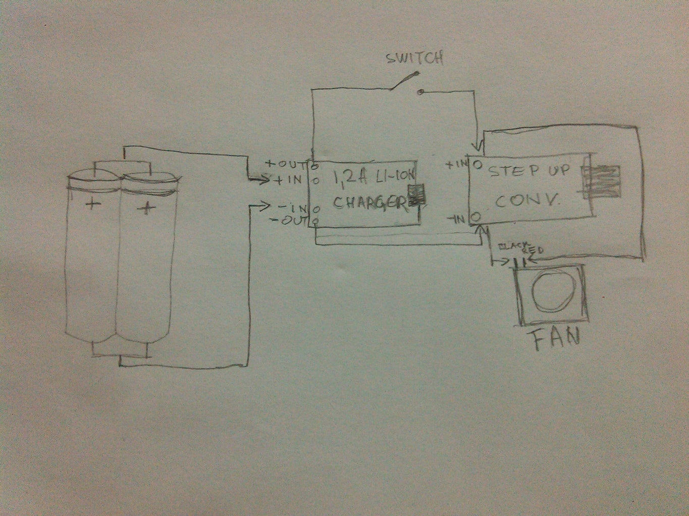
After collecting all the parts, you should build a improvised circuit to test the bank.
Use the circuit from the photo.
The 50-55C° bank working temperature just scared me so I made an aluminium heat sink for the converter (booster), and one for for the charger plus the FAN.
The temperature dropped down to 18-25C°.
Dimensions of the heat sinks and how they are made writes in 4th step...
Step 3: Preparing the Case


A dead laptop charger would look great as a power bank case, of course chargers are different, and as you know it is very hard to open a laptop charger.
Use the dremel for cutting apart the charger.
After taking out the inside parts, straighten the cut middle on a sandpaper for better looking and gluing in the end...
Step 4: Heatsinks


First heat sink is for the booster.
Dimensions are 19x12 x3mm. Cut it as I did and straighten it on sandpaper. Thermal paste would do a lot of good work if you have it.
Of course you need a holder for heat sink but it's hard to tell you the dimensions, so try to make one as mine on the photos.
Before installing the heat sink desolder the LED and solder two wires instead of it for placing the LED on a visible place in the bank.
The second one, for the Li-Ion charger is from an old desktop motherboard.
Take the heat sink from the southern bridge and cut a corner as the 4th photo shows. Dimensions are 13x10x 6mm.
This time I didn't use a holder. There already was thermal glue so I just stuck them together...
Step 5: Making the Battery Pack


The batteries are wired in parallel. After wiring, isolate the poles with 0,5 or thiner plastic sheet. Dimensions are 20x35mm.
Glue them together with glue gun.
Now, I have a suggestion... I made a mistake with the cut corners... Drill holes instead of them as that one in the left corner...
Step 6: Drilling the Holes


Lets start from the cooler. The hole is Ø19mm. drill a smaller hole first and widen it with the grinding stones until Ø17mm then be careful with ending till Ø19mm to get a perfect hole.
Second easier hole is the switch hole.
Not sure if you will find a switch as mine so make the hole to fit the switch for best possibly looking. My switch is used from an old LCD TV and the hole is Ø8,5mm.
Last holes are for USB ports.
To get best, put all the parts into the case, measure with the caliper and copy the measurements to the other side of the case. After cutting, rasp the holes for better looking.
WORK WITH MAXIMAL PRECISION.
More about the fabric holes of the case(input 220V the square, and output the hole beside the switch) is written in 7th step...
Step 7: Wiring the Notification LEDs


Desolder the LEDs (AVOID OVERHEATING) and solder the wires. Make sure to let enough length to wires. Measure and cut the wires on the hole beside the switch.
Solder carefuly the LEDs (for those who are not informed SMD LEDs have a green arrow on the back which shows you the polarization. The arrow is pointed to the -(minus)pole.) or if you are not sure just hold back how you desoldered them.
Gluing is in the end...
Step 8: Fitting and Wiring All Together

When doing this, don't glue as on the photo... it's my fault, I forgot to take a shot before gluing. Just try all into the case, cut the necesar wires, heat shrinkable tubes also and solder all carefully...
Step 9: Gluing

Use one case part as base, fix the modules, batteries, cooler and switch in the right place, and glue them.
In this step I can't give you to much details so be creative :)
Step 10: Closing and Finishing


Super glue the parts and close the power bank.
Now, a very important step, for good looking, hot glue the fabrical holes (input 220V the square, and output the hole beside the switch with the notification LEDs) and make sure for the glue to be enough hot to be able to stretch on the whole surface. (if the gun doesn't make enough temperature, use hot air desoldering tool... in my next instructables I will post how to make an etil alcohol desoldering tool)
NOTIFICATION LED LIGHTS
1.RED-charging input (6th pic);
2.BLUE-Power bank charged (7th pic);
3.BLUE (my choice)-charging output (8th pic);
4.RED-BLUE combi-charging input plus cooling (switch on) (9th pic).
Tip:
Use LED colors you like.
Step 11: About Project
As every DIY project, and this has advantages and disadvantages, but working with more care you can get much better results.
ADVANTAGES:
•low cost;
•good looks;
•easy to make;
•enough capacity for charging 1,5-2 times (depending on your phone battery capacity);
•air cooling system;
•notification LEDs place;
DISADVANTAGES:
•No battery level indicator;
•6 hours charging for full charge;
•to much input current overheats the charging module even if it is a 1,2A (850mA is charging 6 hours at 21C°)
•The FAN is draining too much current;
TIPS FOR SOLVING PROBLEMS:
As you know, opening the bank again is not preferably now when done so I can give you some tips for trying to make it better before closing.
•Battery level indicator would be great on this project but I could not find the right thing on the WEB, at least not in my country.
There is possibility to make the indicator, even a simple one with two zener diodes, two resistors and two LEDs, or a more precisely one with 4 LEDs, IC LM399N some resistors and capacitors. The first possibility is easy but I did not need it. The second one is better but taking to much place so I said no also.
More about indicators find on WEB (ex:electroschematics.com)... If you decide to use a indicator, chose the one you like, make it, buy it or use it from an old power bank...
•The FAN... Making problems with draining the cells...
You have two options that I forgot to try when the bank was opened:
-Try to wire the FAN to output of the step up module... It would work fine but the charging would be little slower but the bank would be able always to keep the FAN working constantly and let the cells to discharge to minimum.
-Just don't wire the FAN... The bank would also work but the modules temperature would be around 35C° with heat sinks. Without heat sinks it goes up to 57C°.
If you glue the modules with hot glue, it is not wise to let overheating dominate. The modules will just move from the place you fixed them, this is why I let the FAN wired.
One more idea... if you install the FAN, you can put another switch for starting and stopping it at wishing time.
•IDEAS
-If you have enough place into the bank case, install one or more white 5mm LED with a momentary switch and use it as flashlight.
-Install a solar panel on one side of the bank for additional charging and it will be full charged almost always when it is at sun light.
-The on/off switch could be a momentary like Click-on/Click-off or Hold-on/Click-off etc...
It can be made with logic gates, 555 timers or transistors but it takes to much place into the case.
-If you install a battery indicator with automatic low battery activation LED, you could fix inside a little vibrator motor from an old cell phone instead of LED... Of course it's not standard, but it would surely notify with low vibrations when the battery is getting low.
•END
I wish you all the best for building the power bank... For sure it wont be perfectly as mine so try to use your imagination and creativity to make one better then mine even with similar parts...
If you like the project and decide to build it and have any important questions message me on facebook (address is written on my instructables profile) and here I am to help :)
See my other projects and be sure there will be a lot more...
GOD BLESS!
UPDATE
I just decided to cut off a wire from the FAN.
I measured the charging output current on an app and it is 830 m Ah. I can now charge my phone 3 times with one charging of the power bank and its amazing.
Didn't expect from that FAN to drain that much current... and yes... advices, critics, and questions are welcome.


