Introduction: DIY Wireless Joystick (Wireless Gaming)
In this instructables I will show you how you can build your own joystick using Arduino and RF transceiver. I used a joystick module and 5 buttons. Using joystick you can control mouse cursor & using buttons you can implement 5 keys of the keyboard. I implemented W, A, S, D and Space as these are the most commonly used buttons for games. You can implement your own choice. There are two units for the system, transmitter (your joystick) & receiver connected to your PC. You may use any Arduino board or standalone ATmega microcontroller for the transmitter unit but it is convenient to use Arduino Micro, Pro Micro, DUE or Leonardo for the receiver unit because all the board used 32U4 controller comes equipped with a full-speed USB transceiver. Low cost 433MHz RF transceiver was used for wireless communication.
I always miss 3D printer when build any project. You can make a cool 3D for printed cage if you have access to 3D printer to bring more professional look.
You can easily modify it to work as wireless keyboard, wireless mouse or wireless presenter.
Step 1: What You Need
COMPONENTS
- Arduino Micro (Seeedstudio) or Pro Micro (Sparkfun)
- Arduino Pro Mini (Seeedstudio) or ATmega328
- Grove - Thumb Joystick (Seeedstudio)
- 315Mhz RF link kit (Seeedstudio)
- Tactile Button (5pcs) (Sparkfun)
- Polymer Lithium Ion Battery (Sparkfun)
- Lithium Battery Charger Module (Dfrobot)
- USB Male Type A Connector (Sparkfun)
- Vero Board
- Jumper wire
- A LED & 220 ohm resistor
- On/Off Switch
HAND TOOLS
- Soldering Iron
- Wire Cutter
- Hot Glue Gun
- Desoldering pump
Basic soldering skill is required to make the project successful.
Step 2: Making the Receiver (Little Desoldering)
My wireless joystick has two parts. One is receiver which will be connected to PC via USB port. Another is transmitter and this is the actual joystick in your hand. As I mentioned earlier, Receiver unit should contains 32U4 comes equipped with a full-speed USB transceiver. For the purpose I used cool & tiny Pro Micro from Sparkfun. You may used others variant like Arduino Micro or DUE.
Let's make receiver first as it has less connections required. I assumed you have some soldering experience, if not you may try this instructables (How-to-solder).
I used 433MHz FM receiver with the Pro Micro to receive signal from joystick. First, you need to desolder 4 pins header from the receiver unit. It will help you to easily adjust the receiver to Pro Micro board.
Step 3: Making the Receiver (Connecting Pro Micro to RF Receiver)
Now, you should connect the RF receiver to the Pro Micro. RF receiver has 4 pins. One for VCC, one for GND and rest two pins for data. Connect VCC pin to Pro Micro's VCC pin & GND to Pro Micro's ground. Basically two data pins are one pin. You can connect any one to the Pro Micro's I/O pin. You may use any of the I/O pin but I used pin 9 of Pro Micro. I used jumper wire to connect two things together like figures.
After soldering you have to fix two things together. For that I used a insulator between them otherwise these may short circuited accidentally and may damaged the receiver or Pro Micro.
Step 4: Making the Receiver (Uploading the Program)
If you followed the previous steps you are in the final stage of making receiver. Use glue or tap or band to fix all the things. I used rubber band to do the job. Pictures are added. Finally you need a USB cable to to connect it with the PC. I missed one thing. You may used a short piece of jumper wire as antenna which will increase the rang of your wireless joystick.
I think you already made your receiver. Just upload the following program to the receiver to make it complete. You will notice in the sketch three library ware used. Keyboard and Mouse library is included to Arduino IDE but you have to add VirtualWire library to talk to RF receiver.
You can learn more about keyboard and mouse library from Sparkfun tutorial.
#include <Mouse.h>
#include <Keyboard.h>
#include <VirtualWire.h>

const int led_pin = 13;
const int transmit_pin = 11;
const int receive_pin = 9;
const int transmit_en_pin = 3;

#define KEY_UP_ARROW   0xDA
#define KEY_DOWN_ARROW 0xD9
#define KEY_LEFT_ARROW 0xD8
#define KEY_RIGHT_ARROW    0xD7
#define KEY_BACKSPACE  0xB2

void setup()
{
    delay(1000);
    Serial.begin(9600);  // Debugging only
    Serial.println("setup");

    // Initialise the IO and ISR
    vw_set_tx_pin(transmit_pin);
    vw_set_rx_pin(receive_pin);
    vw_set_ptt_pin(transmit_en_pin);
    vw_set_ptt_inverted(true); // Required for DR3100
    vw_setup(2000);  // Bits per sec

    vw_rx_start();       // Start the receiver PLL running
}

void loop()
{
    uint8_t buf[VW_MAX_MESSAGE_LEN];
    uint8_t buflen = VW_MAX_MESSAGE_LEN;

    if (vw_get_message(buf, &buflen)) // Non-blocking
    {
      digitalWrite(led_pin, HIGH); // Flash a light to show received good message
      // Message with a good checksum received, print it.
      Serial.print("Got: ");

      Serial.println((char)buf[0]);
      char c = (char)buf[0];

      if(c=='W'){
      Keyboard.write('w');
      delay(100);
      }

      if(c=='A'){
      Keyboard.write('a');
      delay(100);
      }

      if(c=='S'){
      Keyboard.write('s');
      delay(100);
      }

      if(c=='D'){
      Keyboard.write('d');
      delay(100);
      }

      if(c=='U'){
      Keyboard.write(KEY_UP_ARROW);
      delay(100);
      }

      if(c=='B'){
      Keyboard.write(KEY_DOWN_ARROW);
      delay(100);
      }

      if(c=='L'){
      Keyboard.write(KEY_LEFT_ARROW);
      delay(100);
      }

      if(c=='R'){
      Keyboard.write(KEY_RIGHT_ARROW);
      delay(100);
      }

      if(c=='G'){
      Keyboard.write(KEY_BACKSPACE);
      delay(100);
      }

      if(c=='1'){
      Mouse.move(0,5,0);
      delay(100);
      }

      if(c=='2'){
      Mouse.move(0,10,0);
      delay(100);
      }

      if(c=='3'){
      Mouse.move(0,15,0);
      delay(100);
      }

      if(c=='4'){
      Mouse.move(0,20,0);
      delay(100);
      }

      if(c=='5'){
      Mouse.move(5,0,0);
      delay(100);
      }

      if(c=='6'){
      Mouse.move(10,0,0);
      delay(100);
      }

      if(c=='7'){
      Mouse.move(15,0,0);
      delay(100);
      }

      if(c=='8'){
      Mouse.move(20,0,0);
      delay(100);
      }
   }
}
Step 5: Making the Transmitter (Soldering Buttons & IC)
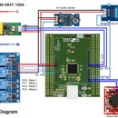
Our receiver unit is ready. Now, it is the time to make main thing the joystick. I used one x-y axis joystick module and 5 momentary buttons for the things. For the shortage of time I used veroboard for the complete task but a PCB board will definitely make it more reliable and more beautiful. I think a typical veroboard is enough. Fritzing board layout for the complete system with source file are attached below.
First, solder 5 momentary buttons at the right side of the board. Then put and solder a 28 pins IC base at the middle of the board. Ic base is not mandatory byt I always prefer to use it. It protects the IC from burning during soldering and it makes the IC movable.
Attachments
Step 6: Add Jumper Wires to Connect Buttons With IC
One thing I should mention here, I used Standalone ATmega328 microcontroller instead of Arduino Pro Mini. You can used as you like. A 16 MHz crystal is required and for that I soldered it with the board. I also add a on/off button with a indicator LED. Do not forget to used a 220-330 ohm current limiting resistor with led.
Step 7: Making Joystick (Connecting RF Transmitter and Li-ion Charger)
Now, connect the RF transmitter to the board. RF transmitter has three pin. One for data transmission and another two pins for biasing. Data pin need to connect one of the digital I/O pin of Atmega microcontroller. I used pin 9 of Arduino which is pin physical pin 15 of ATmega328.
After connecting RF transmitter I connected Li-ion charger module to chard the battery which I will connect later to the board. You should use some glue to fix it with the board strongly. Hot glue may be a good option.
Step 8: Making Joystick (Connecting Joystick Module)
Now connect joystick module to the board which will act as a mouse for greater experience of gaming. Joystick's has 5 pins. Two for VCC and ground. Actually joystick's has tow potentiometer and the value of the potentionmeter changes for rotating the nob. One pot is for X - axis and another is for Y - axis. Two analog input pins are required for connecting. I used A0 and A1. Joystick has one switch also which may be used to identify mouse click. Used any of Arduino digital pin to connect. it.
Step 9: Connecting the Battery
Now you have to connect the rechargeable Li-ion battery to the board. Connect it according to the circuit. Battery should be fixed with the board tightly. I used double sided tap for the purpose.
After connecting battery connect a charger port to the charging module. I you done all thing correctly your battery will start charging. Test it.
Step 10: Uploading of the Program
All connections and soldering are completed. It is the right time to program the board. I developed the rogram using Arduino IDE. Then I burned the program to the IC using Arduion UNO and then put the IC to the board. If you like to used only atmega IC like me instead of using full arduino board you may follow this tutorial (From Arduino to a Microcontroller on a Breadboard).
Here is the program I used for my joystick. I also added the file below. Arduino VirtualWire library was used for interfacing with RF transceiver.
//..................................
#include <VirtualWire.h>

const int led_pin = 13;
const int transmit_pin = 9;
const int receive_pin = 10;
const int transmit_en_pin = 3;

int horzPin = A0;  // Analog output of horizontal joystick pin
int vertPin = A1;  // Analog output of vertical joystick pin
int selPin = 11;  // select button pin of joystick

int vertZero, horzZero;  // Stores the initial value of each axis, usually around 512
int vertValue, horzValue;  // Stores current analog output of each axis
const int sensitivity = 200;  // Higher sensitivity value = slower mouse, should be <= about 500
int mouseClickFlag = 0;

char *controller;
String msgV, msgH;
int W=8, A=6, S=5, D=7, SPACE=2;
void setup() {
    pinMode(13,OUTPUT);
    delay(1000);
    Serial.begin(9600);  // Debugging only
    Serial.println("setup");

  pinMode(horzPin, INPUT);  // Set both analog pins as inputs
  pinMode(vertPin, INPUT);
  pinMode(selPin, INPUT);  // set button select pin as input
  digitalWrite(selPin, HIGH);  // Pull button select pin high
  delay(1000);  // short delay to let outputs settle
  vertZero = analogRead(vertPin);  // get the initial values
  horzZero = analogRead(horzPin);  // Joystick should be in neutral position when reading these

    // Initialise the IO and ISR
    vw_set_tx_pin(transmit_pin);
    vw_set_rx_pin(receive_pin);
    vw_set_ptt_pin(transmit_en_pin);
    vw_set_ptt_inverted(true); // Required for DR3100
    vw_setup(2000);  // Bits per sec

    pinMode(5, INPUT);
    pinMode(6, INPUT);
    pinMode(7, INPUT);
    pinMode(8, INPUT);
    pinMode(2, INPUT);

    digitalWrite(5, HIGH);
    digitalWrite(6, HIGH);
    digitalWrite(7, HIGH);
    digitalWrite(8, HIGH);
    digitalWrite(2, HIGH);

    delay(1000);
}

void loop(){

  vertValue = analogRead(vertPin) - vertZero;  // read vertical offset
  horzValue = analogRead(horzPin) - horzZero;  // read horizontal offset

  if(digitalRead(W)== LOW){
    controller="W";
    vw_send((uint8_t *)controller, strlen(controller));
    vw_wait_tx(); // Wait until the whole message is gone
    delay(100);
    }
   if(digitalRead(A)== LOW){
    controller="A";
    vw_send((uint8_t *)controller, strlen(controller));
    vw_wait_tx(); // Wait until the whole message is gone
    delay(100);
    }
   if(digitalRead(S)== LOW){
    controller="S";
    vw_send((uint8_t *)controller, strlen(controller));
    vw_wait_tx(); // Wait until the whole message is gone
    delay(100);
    }
   if(digitalRead(D)== LOW){
    controller="D";
    vw_send((uint8_t *)controller, strlen(controller));
    vw_wait_tx(); // Wait until the whole message is gone
    delay(100);
    }

   if(digitalRead(SPACE)== LOW){
    controller="G";
    vw_send((uint8_t *)controller, strlen(controller));
    vw_wait_tx(); // Wait until the whole message is gone
    delay(100);
    }

   if (vertValue >= 50){
    //Mouse.move(0, vertValue/sensitivity, 0);  // move mouse on y axis
     if(vertValue/sensitivity ==1)
       controller = "1";
     else if(vertValue/sensitivity ==2)
       controller = "2";
     else if(vertValue/sensitivity ==3)
       controller = "3";
     else
       controller = "4";
    vw_send((uint8_t *)controller, strlen(controller));
    vw_wait_tx(); // Wait until the whole message is gone
    delay(100);}
   if (horzValue >= 50){
     if(horzValue/sensitivity ==1)
       controller = "5";
     else if(horzValue/sensitivity ==2)
       controller = "6";
     else if(horzValue/sensitivity ==3)
       controller = "7";
     else
       controller = "8";
    vw_send((uint8_t *)controller, strlen(controller));
    vw_wait_tx(); // Wait until the whole message is gone
    delay(100);}
}
Step 11: Making Cage
I have no access to any laser cutter. If you have you can make nice box for the joystick.
I have made a box using PVC sheet. Cut to pieces of PVC sheet according to your PCB. Attach one piece of the board to the bottom side of PCB. You have to make some hole to the top piece for the buttons, power LED & joystick. I used tracing paper to trace the buttons position. Images are attached. Then I used a knife to make hole to the top sheet. Then I fixed it to PCB by hot glue.

Participated in the
Gaming Contest

Participated in the
Hand Tools Only Contest 2016


