

Introduction: Designing a PC Case From Scratch

About a year ago, I decided that I wanted to design the smallest production-quality PC case that can house the most powerful components. This means water-cooling, full-sized graphics card, overclocking, the whole shebang. But I didn't want it to be a one-off project. I wanted it to be mass produced so I can help end the stagnant state of PC case design.
The problem is, I didn't know anything about designing a case, and I barely knew how to use CAD. So the first thing I could come up with was this.
Step 1: The First Iterations

To get an idea of how much this would cost to produce, I emailed my "design" to manufacturers all over the world. Anyone that I can find on google. Only about 10% responded. Everyone else took one look at what I got and immediately concluded that it was unmanufacturable, and that a complete novice was behind this design. One company responded just to jeer at me.
Some of the mistakes I made are:
- All bends are perfect 90 degree angles, which is impossible to make. I found out that typically for sheet metals, the outer bend radius = 0.3mm + sheet thickness.
- Some holes are too closed together or too big/small. I found out that typically, any hole that is punched cannot have diameter less than the sheet thickness. The holes also should be spaced at least 1.5x-2x the sheet thickness apart, or the sheet will distort.
Step 2: The Pre-Prototype

Even though it was discouraging, I did learn a lot from the manufacturers. I decided to take advantage of a school event to make a super preliminary prototype of my design. I had divided the parts into 6 separate metal sheets, and I wanted to know if what I had in mind is even remotely possible and... well, it was ugly and the fit was poor, but it seems to work.
Step 3: Deep in Design

Armed with physical intuition from building the pre-prototype, I began round after round of design improvements. Aside from trying to have the case hold many combinations of components, my focus was making the case as quick (and thus cheap) to manufacture as possible. This includes making decisions like:
- Have as little bends as possible.
- Design the case to be assembled from bent metal sheets without any need for welding.
- Reduce the number of punched holes, instead increasing the hole size to maintain the same total hole area.
- Reduce the number of openings that cannot be created by punching holes (has to be laser cut).
- Use only one hole size, so the hole-punching tool does not have to be swapped out during the whole process.
Step 4: !nverse: Finalized

Many iterations later, the design is reaching maturity. Able to hold 4 different configurations, including a 240mm AIO water cooler, a full-size GPU, and large 3.5" hard drives, it emerged as one of the most versatile "flat" case designs ever conceived.
Step 5: The First Prototype

While I was deep in the design of things, my friend contacted nearly 200 manufacturers all over the world. We sent each of them CAD drawings after CAD drawings, begged for their advice, until the design finally became manufacturable. And then we selected one manufacturer to make a prototype for us.
Step 6: The First Prototype (cont.)

Giddy with excitement, we tore the nicely wrapped package apart to reveal our prize.
Step 7: The First Prototype (cont.)

We made this!!
Step 8: The First Prototype (cont.)

Very nice, but will it run?
Step 9: The First Prototype (cont.)

The empty interior skeleton, ready for component installation.
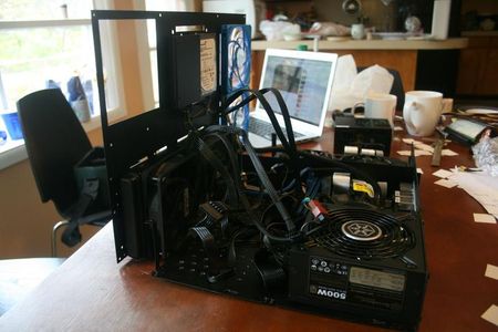
Step 10: The First Prototype (cont.)

IT LIVESSSSSS!!!!!!
So what components can it hold?
Step 11: Picture of Interior Configuration 1

mITX motherboard, full size GPU, 120mm AIO water cooler, SFX/SFX-L power supply, 2 x 3.5" HDD, 2 x 2.5" SSD, 2 x slim 120mm fan
Step 12: Picture of Interior Configuration 1 - Closed

Step 13: Picture of Interior Comfiguration 2
mITX motherboard, full size GPU, 240mm AIO water cooler, SFX power supply, 2 x 2.5" SSD, 2 x slim 120mm fan
Step 14: Picture of Interior Configuration 2 - Closed

Step 15: Picture of Interior Configuration 3

mITX motherboard, full size GPU, low profile air cooler, SFX/SFX-L power supply, 3 x 3.5" HDD, 2 x 2.5" SSD, 2 x slim 120mm fan
Step 16: Picture of Interior Configuration 3 - Closed

Step 17: Picture of Interior Configuration 4

mITX motherboard, low profile air cooler, SFX/SFX-L power supply, 6 x 3.5" HDD, 4 x 2.5" SSD
Step 18: Picture of Interior Configuration 4 - Closed

Step 19: The !nverse Case Project

We ran thermal tests, structural tests, and check component fitment. Everything worked great! Here are the detailed thermal tests for the first prototype:
http://hardforum.com/showpost.php?p=1041886278&postcount=270
Taking what we learned, we tweaked some small details and then sent off the second prototype design to our manufacturer. Right now, we are expecting the second prototype in a few weeks.
This has been an unbelievable journey, but we're not done yet. For those of you who want to keep up-to-date with the !nverse case project, please follow us here:
https://rationalbananas.wordpress.com/followcontact-us/
Thanks for reading!


