

Introduction: Dieselpunk FPV Tractor


Introduction
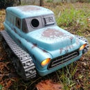
Do you long for an alternate universe where robots race ratty boat-tailed tractors at mindbogglingly low speeds? Now you can print your own, fire up your FPV goggles and get behind the wheel yourself!
I took great care to make this project easy to print (no supports needed) and assemble, as well as, I hope, a lot of fun.
There is a lot of room for customization too, you will see I have already released alternate hood designs and a variety of tracks. The motor mounts are modular so that you can use servos or motors (or leave them out altogether and make a push toy!)
If you don't feel like doing an FPV build then there is a cool head that goes in place of the camera.
I designed the whole project in Fusion360, except for the head, which was modeled by my friend Fotis Mint in ZBrush. I printed mine on the RoboxDual, so it is easily achievable with a small build volume.
Full Build Video
I heartily recommend that you watch this video which has some driving footage and also shows you the full build process (minus the electronics), including: body assembly, track assembly, driver assembly and paint.
Step 1: You Will Need...


STL Files
- Original Version
- Racer Version (some alternate hoods and motor mounts)
- Alternate Tracks (suitable for flexible filament)
- Third Party Option Parts (notify me of your mods and I'll add them here):
Mechanical Parts
- Bearings: 6700ZZ 10 X 15 X 4 (qty. 8)
- M3x8 Countersunk Screws (qty. 4)
- M3x10 Cap Screws (qty. 16)
- M3x12 Cap Screws (qty. 4)
- 8x2mm Round Magnet (qty. 6)
The screw lengths are actually not too prescriptive, you can go longer/shorter by a couple millimeters in most cases without affecting the build.
Electronics
- See the electronics step for more details, the following is a typical build
- Continuous Rotation Servos (qty 2)
- Micro Servo (qty 1)
- RC Transmitter and Receiver (with mixing capability)
- FPV Camera and Transmitter
- 5V Voltage Regulator
- LiPo Battery
Tools
- 3D Printer
- Soldering Iron
- Screw Driver/Allen Keys
Consumables
- Paint (I used acrylic and spraypaint)
- Super Glue
- Filament (I used Rigid.Ink PETG, ABS and TPU and FormFutura ABS)
Step 2: Print the Files


I have designed almost all of the files to be printed without the use of supports (Only exception being the driver's head, which is a sculpted piece, and the driver base, which has a channel for wires - both are labelled as needing supports in the file names).
Depending on your slicer you should find that the parts are orientated correctly already, but I have included pictures in this step that show the ideal orientation.
Printer
You should be able to print this project on almost any printer, but I certainly appreciated the excellent bed adhesion on the RoboxDual when printing all the track segments.
Material
There is no specific material required, I have used ABS for most of my builds, but the parts are fairly forgiving and should be achievable in most materials.
The one exception is the base for the driver ("driver base - use supports.stl"), the post will be far stronger if it is printed in PETG (or nylon if you want to go nuts).
Printer Settings
I have designed the thin parts (the body panels mostly) to be even multiples of 0.4mm (2.4mm in fact) meaning that they will print cleanly and solidly if you choose 3 or more perimeters.
Step 3: Mechanical Assembly: Vehicle


In order to complete the mechanical portion of the build you will need the following items
Mechanical Parts
- Bearings: 6700ZZ 10 X 15 X 4 (qty. 8)
- M3x8 Countersunk Screws (qty. 4)
- M3x10 Cap Screws (qty. 16)
- M3x12 Cap Screws (qty. 4)
- 8x2mm Round Magnet (qty. 6)
Assembly Animation
This animation will show you the assembly process (for those curious, this was done inside the Fusion360 Animation workspace, which turns out to be quite easy to use, so long as you plan your animation carefully)
Step 4: Mechanical Assembly: Driver


Overview
The driver is a slightly different assembly and from the perspective of "design for printing" the arms are probably the most interesting part of the project (to me anyway)/
I needed a lot of freedom of movement, so that the steering wheel servo could make the arms move, without putting much strain on it.
I also wanted to avoid fiddly assembly and printing with supports, so I came up with a three-piece design that results in 5 axes of movement.
Two of the joints are simple pivots using 1.75mm filament off-cuts as hinges, but the others are print-in-place, as shown in the attached pictures. These are the sorts of things that would be impossible to do with traditional manufacturing methods. Be sure to read the annotations on the pictures if you want to know more.
The assembly of these joints can be seen at the 7 minute mark of the full build video (in Step 1).
Arm Assembly
In case you can't watch the video:
- Use superglue to attach the shoulder joint to the torso (outside ring only, don't get glue on the center bit!)
- Insert the upper arm and use a piece of filament as a hinge-pin, putting a drop of glue on the ends to keep it in place (this arm needs to be gently twisted to break the built-in support)
- Insert the lower arm in the same way. In this case the hand needs to be twisted to break it free.
Head Assembly
The camera head and the decorative head are both attached using the same press-fit neck design. If the fit is too tight you may want to sand it gently.
Step 5: Electronics


There are a huge number of ways that you could tackle the electronics on these builds. My goal was to be able to records HD video, and I was not particularly concerned about speed, so I choose to use a Runcam Split 2 as the camera and hacked servos as the motors.
I have tried to make the design as modular as possible, so there are a number of ways you can build it, depending on your budget and requirements.
The biggest challenge is space, so if you have access to a micro receiver that will help a lot.
Driving the Tracks: Hacked Servos
A hacked servo is simply one which has been converted to continuous rotation, by breaking the feedback loop and removing the mechanical restrictions. It is beyond the scope of this instructable, but you can find more info HERE if you need it, or simply purchase a premade continuous rotation servo.
Pros of servos
- They have great torque (due to their low gearing)
- Easy to control (no ESC needed)
Cons of Servos
- Very slow (due to low gearing)
- Most are limited to 5V, so you will require a BEC (voltage regulator)
Driving the Tracks: Gear Motors
An alternate option is to use gearmotors. I have designed two alternate motor mounts, for two different options, but I have not yet built one myself. I would love to hear your results though if you do!
You can find the motor mounts here
If you decide to use motors you will need to source two ESCs (or a dual ESC)
FPV System
The very simplest way of achieving the FPV feed would be to use an "AIO" (all in one) camera as commonly used on Tiny Whoops (Such as the CM275T). These cameras are tiny and include a video transmitter, all they need is 5V for power. I have drawn a schematic of this option, but it is not what I used.
I wanted to be able to record HD video, so I used the excellent RunCam Split 2 (which records to an SD card at the same time as putting out an analog video feed) and a separate 200mW VTX (Video Transmitter). I have included a schematic of this option too.
Example Build
The following is an example build, and is what I used for mine.
Step 6: Alternate Builds


Track Options
If your printer can handle flexible filaments then you can try out one of the variety of weird and wonderful flexible tracks that I have designed, they all use the same drive sprockets.
The flexible tracks can be found here. Big thanks to Fred Kaz for sharing photos of his build for this step.
Motor Options
There are two optional motor mount files,which can be found here
- The F280 motor is held in place by 2.5mm zip ties
- The JGA25-370 has holes for mounting screws in its front face
Push Toy Build
While the RC build is good fun for us grown-up children the real kids might just like it as a push toy, this can easily be achieved be using the files for the servo build and simply not installing any servos, the tracks will freewheel nicely.
Step 7: Alternate Finish


The pictures in this step are an alternate build that I did using rigid.ink's awesome pearl red and silver ABS filaments, followed by an acetone vapor bath.
The vapor bath is due its own Instructable (and there are plenty), but the short of it is that the parts are placed into a Tupperware container full of acetone vapor, which slowly dissolves the ABS, this process stops when the parts are removed and they become hard again over the course of a few hours, resulting in a nice shiny surface.

First Prize in the
Toys Contest


