

Introduction: Distance Detector


To create distance sensor (distance detector) using basic components like arduino, ultrasonic sensor, buzzer and leds. The ultimate goal of this project is check how far is the object from the sensor using the help of buzzer and leds.
Step 1: Components Required


1-Arduino uno.
2-Breadboard
3-Stepper wires (male to male, male to female)
4-Substantial amount of green, yellow and red leds(light emitting diodes)
5-Buzzer(one can use both 0-5V buzzer or 3-27V buzzer)
6-HC-SR04 Ultrasonic sensor
7-330ohm resistors( at least 7)
8-9V battery
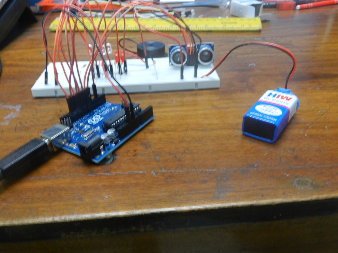
Step 2: Setup Design

The photo above shows the setup of the project. The jumper wires should be connected as follows:
Connect a jumper wire from the 5 volt pin on the Arduino to the bottom channel of the breadboard
Connect another jumper wire from a ground pin on the arduino to the upper channel of the breadboard
Buzzer -> pin 3
(On Ultrasonic Sensor)
Echo -> pin 6
Trig -> pin 7
(In Order from Right to Left)
LED1 -> pin 8
LED2 -> pin 9
LED3 -> pin 10
LED4 -> pin 11
LED5 -> pin 12
LED6 -> pin 13
The jumper wires connected to the LEDs should be connected to the lead on the right, while the left lead of the LED should connected to the ground channel via a 330 ohm resistor
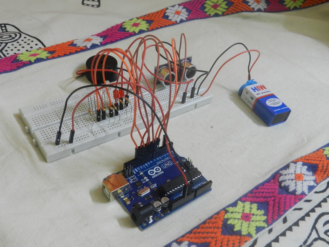
Step 3: Assembly-Breadboard

First connect the 5V and ground pin from the Arduino to the breadboard.
-Connect the wire from the 5V pin of the Arduino to the bottom channel on the left half of the Breadboard.
-Connect the wire from the ground pin of the Arduino to the upper channel on the left half of the Breadboard.
Step 4: Ultrasonic Sensor


Connect the HC-SRO4 to the upper right half of the breadboard.Refer the setup diagram provided in the earlier diagram while making the connections.From the earlier setup diagram, one should connect the ground pin on the ultrasonic sensor to the ground channel on the breadboard. Next connect the Echo pin on the sensor to pin 6 on the Arduino. Now connect the Trig pin on the sensor to pin 7 on the Arduino, and lastly connect the VCC pin on the sensor to the 5 volt channel on the breadboard.
Step 5: LED Connections

Next step involves connecting the Leds to the breadboard and the arduino. The way to connect them is to connect the anode, or the longer leg, or the one on the right, to a pin on the Arduino with a jumper wire, and to connect the cathode, or the shorter leg, or the one on the left, to the ground channel on the breadboard using a 330 ohm resistor. Then just repeat that step for all six of the LEDs, with the red LED all the way on the right being connected to pin 8 on the Arduino, the anode of the red LED to the left of that one being connected to pin 9 on the Arduino, and so on. The last LED, that being the green LED all the way on the left, should have it's anode, or right leg, connected to pin 13 on the Arduino.
Step 6: Connect the Buzzer and the 9V Battery


Now we have to attach the buzzer to the arduino and the breadboard.One has to connect the longer leg of the buzzer to pin 3 of the Arduino and attach the shorter leg of the buzzer to the ground channel of the breadboard.Also connect the 9V battery to the live and ground channel on the right half of the breadboard..
Step 7: The Required Code
- Required code to run the Arduino program in order to achieve the required aim is given below-
#define trigPin 7
#define echoPin 6 #define led 13 #define led2 12 #define led3 11 #define led4 10 #define led5 9 #define led6 8 #define buzzer 3int sound = 250;
void s etup() { Serial.begin (9600); pinMode(trigPin, OUTPUT); pinMode(echoPin, INPUT); pinMode(led, OUTPUT); pinMode(led2, OUTPUT); pinMode(led3, OUTPUT); pinMode(led4, OUTPUT); pinMode(led5, OUTPUT); pinMode(led6, OUTPUT); pinMode(buzzer, OUTPUT); }
void loop() { long duration, distance; digitalWrite(trigPin, LOW); delayMicroseconds(2); digitalWrite(trigPin, HIGH); delayMicroseconds(10); digitalWrite(trigPin, LOW); duration = pulseIn(echoPin, HIGH); distance = (duration/2) / 29.1;
if (distance <= 30) { digitalWrite(led, HIGH); sound = 250; } else { digitalWrite(led,LOW); } if (distance < 25) { digitalWrite(led2, HIGH); sound = 260; } else { digitalWrite(led2, LOW); } if (distance < 20) { digitalWrite(led3, HIGH); sound = 270; } else { digitalWrite(led3, LOW); } if (distance < 15) { digitalWrite(led4, HIGH); sound = 280; } else { digitalWrite(led4,LOW); } if (distance < 10) { digitalWrite(led5, HIGH); sound = 290; } else { digitalWrite(led5,LOW); } if (distance < 5) { digitalWrite(led6, HIGH); sound = 300; } else { digitalWrite(led6,LOW); } if (distance > 30 || distance <= 0){ Serial.println("Out of range"); noTone(buzzer); } else { Serial.print(distance); Serial.println(" cm"); tone(buzzer, sound); } delay(500); }
Step 8: Result
Now upload the program to the Arduino and run it.If proper connections are given, as we bring our fingers very close to the ultrasonic sensor, the leds will start glowing and the buzzer will emit a sound .
Applications
This model can be used as a sort of reference for Car Rear Parking System.
--Experimental demonstration of the video has been shown in the above two attached files...


