

Introduction: Double Mechanism #1 (in Progress)


For this sculpture, I am really interested in thinking about how mechanical objects, doing the same thing, can be completely dependent on each other to hold themselves up. This project was made during my residency at Autodesk's pier 9 workshop.
This piece falls in line with the body of work I've produced over the last 14 years, which are, basically, mechanisms that are designed only to support themselves. My previous work can be seen at www.dangrayber.com.
At pier 9, I wanted to explore different ways of creating the work I make. This piece was nearly entirely designed with Fusion 360, which I've really only just started using. The pieces were machined on the Haas VF2SS, and the Matsuura MX-330. The pulleys were 3D printed on the Objet Connex printer.
Designing with Fusion 360 and CNC milling the parts really enabled me to produce identical mechanisms, which was important to me for this piece.
Step 1: Concept and Form Development


I started with some really rough scribbles in my sketchbook. They really only function to me as visual bookmarks to the thoughts in my head.
Once I had thought about them for a bit, I started working with Fusion to develop them and virtually make them come to life.
Step 2: Fusion (and Real Life) Assemblies.


The great thing about Fusion, for me, was the ability to move an assembly to make sure it does what it is supposed to. Additionally, because I had easy access to a laser cutter, I was able to cut the pieces out quickly and make a working prototype.
Step 3: Fusion CAM


Probably the most time consuming part of my residency was making toolpaths in Fusion. I came into this project with absolutely no CNC experience, so developing tool paths took some time (and patience).
For most of my parts I used a Lang vise (and lang vase with soft jaws). The lang vises have serrated jaws that are machined in a way that allows the serrations to function as an indexing system. With these I was able to go back and forth between the Haas and the Matsuura, and maintain tight tolerances in my setups.
I needed to use CAD files of the vices themselves to make paths for my parts. It's a pretty amazing system!
Step 4: Start Machining!


After checking out my toolpaths, I headed to the machines! The Haas and Matsuura were somewhat intoxicating to run.
Step 5: Consider How Fast Things Are Going, Have a Baby, 3D Print All of the Parts for Backup.

Between tool pathing, machine time, and taking a week off to have a child, I realized that the likelihood of finishing all of my parts was pretty slim. I printed everything to make sure I would have, at least, a functioning prototype for the final show.
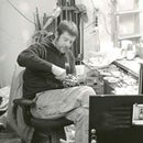
Step 6: Assembly (and Other Stuff).

Aside from the fabrication on the machines, there were some holes that needed to be tapped, bushings and shafts that needed to be machined to size, cables made, and a mount and nearly identical counterweight that had to be made. It was pretty satisfying to finally start assembling parts and see my mechanisms start to take form.


