

Introduction: CNC Drawing Machine


Hello all and welcome to my first tutorial!
Today I am showing you how to design a drawing CNC using as primary Hardware components a Digilent Arty board, DC Motors and RC Servos.
Important Note: Because I am currently working on this project I will show you how to build the CNC and how to control it using Pmod buttons. In the following updates, the Android and Bluetooth part is going to be presented and explained also.
There has been an enormous interest in drawing machines since I have started this project, so my attempt tries to break out of the usual, and will implement realistic abstract portrait drawing techniques, making use of 4 watercolor pen-brushes and 1 sponge. The portrait that will be drawn will be sent in the end via Bluetooth from a phone with a special Android app which I have created using Android Studio and Android OpenCV library. This is how the project will be in the end.
Step 1: Hardware and Materials

For now only the requirements for controlling the CNC via buttons will be shown. The other parts described for the full project will be included and explained here in the following weeks.
In order to build it we will split the project into 3 major subsections: the mechanical part, the electrical part and the software part.
Materials for the mechanical part:
-3 X 1m GT2 Timing Belt
-4 X GT2 pulleys
-3 X 1m threaded rod
-16 X 8mm inner diameter bearing
-16 X 8mm screws( should fit with the bearings)
-70 X 8mm nuts
- 9 X 1m 90 degrees aluminium corner profile (25mm x 25mm)
- wooden planks: 2 X 58cm x 5cm x 2cm, 1 X 24cm x 6cm x 2 cm.
Other materials:
-more screws of various sizes
-screwdrivers
-saw
-a drill, with 3mm and 8mm bits
-duck tape
Materials and hardware for electrical part:
Hardware:
-Arty Board Artix-7 FPGA Development Board
-PmodBTN
-2 X Digilent DC Motor/Gearbox (1:19 Gear Ratio)
-2 X PmodHB5: H-bridge Driver with Feedback Inputs
-2 X GWS Servo: S03TXF STD
-Single Motor Mount
Materials:
-1.5m wire bus
-10 male to female wires
-annnnd more wires
The software part:
-Vivado Design Suite WebPACK
Step 2: Building the CNC


This part took me quite long so I may skip some details. I will try to be as explicit as possible.
1. The axes sliders
-Cut the aluminium corners having the specified dimensions( first figure)
-Drill 8mm holes in them at exact positions
TIPS: Drill a smaller hole at first in that spot (e.g. of 3mm) and then drill the 8mm holes for precision
-add the bearings, screws and nuts to the sliding corners (fig 1)
-cut 4 wood pieces( 2cm thick) and drill an 8mm hole in it at specific position(fig 2)
- cut 8 wooden pieces (5 mm thick and aprox. 5cm x 2.5cm) (fig 3)
2. Setting up the main frame
- take the 3 rods and cut them at specific sizes
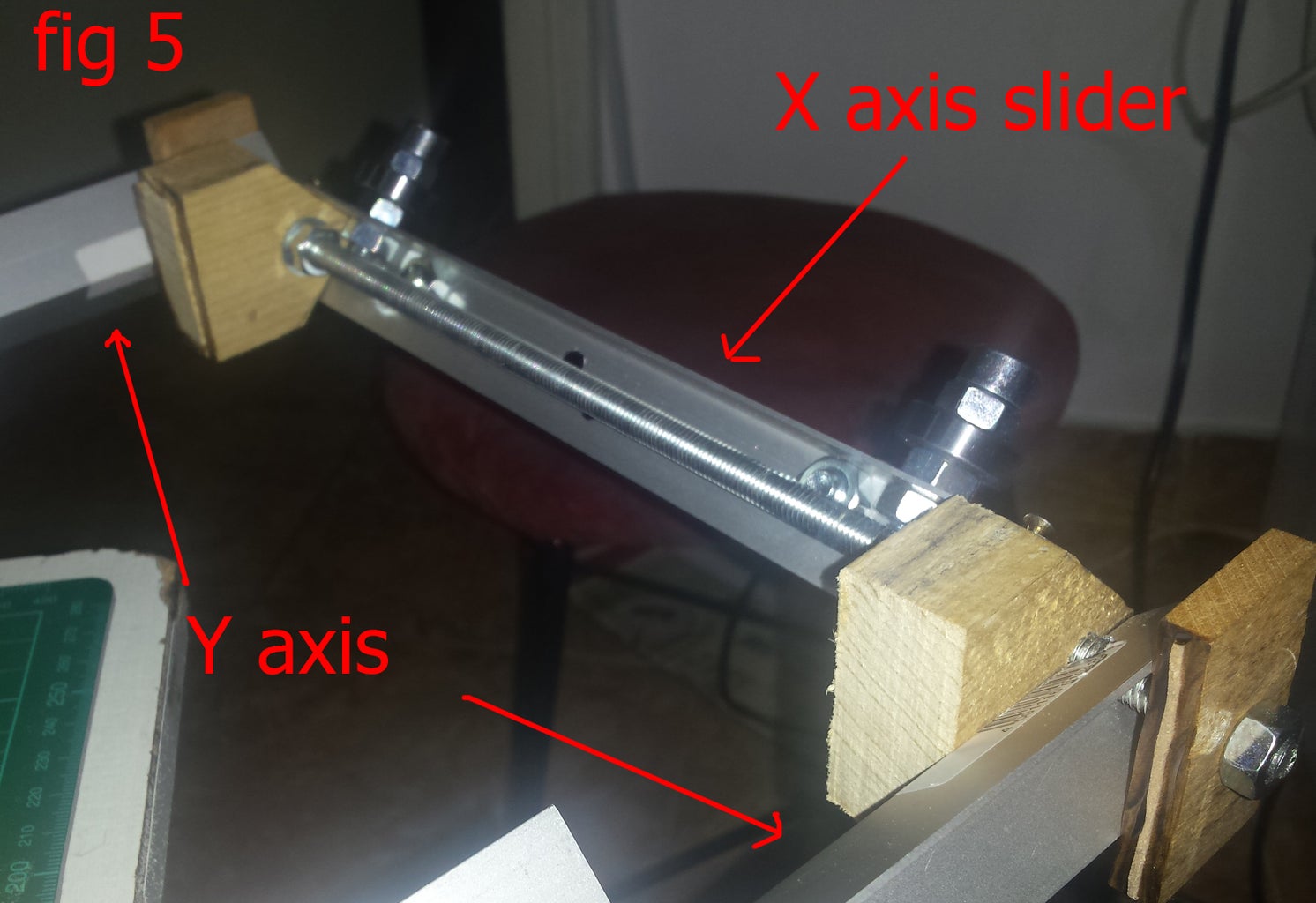
- now install the cut components as in above figure 4 and 5
NOTE: cut some wooden pieces of 5 mm thick ( aprox. 5cm x 2.5cm) - they are used in fig 4 and fig 5
3. Setting up the intermediate frame
-cut a wooden piece( 24cm x 6cm x 2cm ) and make the ends of it pointy just like in fig 2. Arrange it just like in fig 7 drilling holes and using some screws in order to make it stay fix ( fig 6, fig 7)
NOTE: I have mistakenly put one of the sliders the other way around in my project. I did not change it in the end because it didn't make any difference, but it's better to be careful and put it correctly from the start
-assemble the whole CNC and add 2 wooden planks having the same length as the y axis. You can choose any height as long as you know how high you want your CNC to be( fig 8) .
4. Adding the DC motors and servos
- fig 9 and 11 illustrate the position of the DC motors and of the Servos. For designing fig 10 I have also used some Meccano parts. You can improvise in this part if you do not have them.
-When adding the 2 DC's cover the X axis sliders to be able to fix the belt holder and the Y axis DC motor properly.
You should also add a wooden board( or a cardboard) under the CNC. It looks nicer and it is better for the moment the CNC will start drawing
In this part of the pen selector will not do anything so by using duck tape you should tie your crayon to the unused servo or beside it.
TIPS: The belts should not be tight! They should be loosen, or else the system might not work properly.
Step 3: Dealing With the Electrical Part


Good job! Now our CNC is almost ready. Next we need to connect the electrical CNC parts to the board in some way. Because the Digilent 6 pin cable connectors are short, I had to extend the connectors by soldering wires and pins with tin. Fig 12 shows the position of the Arty board in my project. From that position I have used 150 cm of wires for connecting the Y axis DC motor and the Servos. The X axis DC motor has been directly connected to the board using the Digilent cable connector.
According to the position you want your board to stay in I advice you to measure your own wire lengths.
Fig 13 shows you the motors and buttons board connections.
TIPS: The HBridge needs an external power source also. It is best to be of 3.3 V. Because of this I have connected them to the Arty Arduino/ChipKit “shield” connector pin that outputs 3.3 V.
More TIPS: It is best if you connect all the VCC of the motors to an external power source ~ 5 V.
Step 4: Making the CNC Move Properly

The programming part of this project has been done entirely in VHDL, and I preferred to write my own component implementations, although you will find various code examples for controlling the RC Servos/ DC motors.
For controlling both types of motors we will need to implement a PWM (Pulse-width modulation). If you are not familiar with it try searching on the internet for more information. You may also read about how Servos and DC motors work, if you want to find out more.
The PWM period will be different for each type of motor so in the end we will have 2 different codes for pwm for simplicity.
Controlling a DC Motor
The DC Motor is controlled through the H Bridge. In H Bridge datasheet we see that the input enable pin should be connected to a PWM signal and its period should be of 2 KHz. Because the Arty internal clock has 100MHz frequency, in order to get the desired clock period of 2 KHz we will divide 100MHz / 2 KHz = 50000. So I used a counter from 0 to 49999 which refreshes itself when 50000 is reached and forces the PWM output signal '1' and a flag '1'. For the duty cycle i have used another counter that starts counting according to the filling factor when the flag is '1' and when it finishes it forces the flag back to '0'. The filling factors are stored in an array as a constant in the PWMs architecture.
Because we need the DC motor to stop after it moved certain steps, the PWM signal should be 0 in this case so I added another input signal which tells us if the motor should be moving or not. If not, we set output PWM to 0.
In this step of the project the PWM on the DC is a little irrelevant. Its importance will be seen in the next weeks when the DC motor encoder and the PID control will be implemented.
For now, the direction of the motor will automatically be set according to the button pressed.
We control both DC motors in the same way.
Controlling a RC Servo
In this implementation of the project only 1 servo is needed - the up-down servo. The pen selector servo will be shown in the following week.
The Servos input PWM should have a 2ms period. This means a 50 Hz Frequency. Just like before we do the math and we get 2000000 count. The principle is the same as before except that this time we do not care if the PWM signal remains the same ( actually we do, but not in the way we cared for the DC Motor), because a certain factor filling gives us a certain degree for the Servo.
The servo will move according to an input coming from the boards switch. It will either go up, or down( in this position the pen will be on the paper and draw).
A component which binds all the above components together is implemented and is called CNC.
=============The CNC Code=============
---------------DC motor pwm-----------------------
type ROM is array(0 to 4) of integer;
constant my_nums :
ROM :=
( 0 => 0, --0 DC
1 => 12500, --25 DC
2 => 25000, --50DC
3 => 37500, --75 DC
4 => 50000 --100 DC );
signal pwm_temp : std_logic := '0';
signal pwm_temp_cnt: integer := 0;
signal duty_temp: integer := 0;
signal flag2: std_logic := '0';
signal selector : integer:=0;
begin
process (clk)
begin
IF(RISING_EDGE(clk))THEN
if selector = 0 then
pwm_temp <= '0';
elsif pwm_temp_cnt = 50000 then
pwm_temp <= '1';
pwm_temp_cnt <= 0;
flag2 <= '1';
else
pwm_temp_cnt <= pwm_temp_cnt + 1;
end if;
if flag2 = '1' then
if duty_temp = my_nums(selector) then
pwm_temp <= '0';
duty_temp <= 0;
flag2 <= '0';
else
duty_temp <= duty_temp +1;
end if;
end if;
end if;
end process;
process (move_DC)
begin
IF(RISING_EDGE(clk))THEN
case move_DC is
when '1' => selector <= 3;
when '0' => selector <= 0;
when others => selector <= selector;
end case;
end if;
end process;
pwm_clk <= pwm_temp;
---------------DC motor primary component-----------------------
component PWM_DC is
Port ( clk : in STD_LOGIC;
pwm_clk : out STD_LOGIC;
move_DC: in STD_LOGIC);
end component;
signal moveDC: std_logic := '0';
begin
pwm: pwm_dc port map( clk, en_out, moveDC);
----DIRECTION SWITCH---
process(btn)
begin
IF(RISING_EDGE(clk))THEN
case btn is
when "10" => dir_out<='1';
moveDC <= '1';
when "01" => dir_out<='0';
moveDC <= '1';
when others =>dir_out<='0';
moveDC <='0';
end case;
end if;
end process;
--------------------------------RC Servo primary component----------------------
constant my_nums : ROM := (
0 => 80000, --0 1 => 145000, --45 2 => 165000, --90 3 => 175000, --135 DC 4 => 200000 --180 DC );
signal pwm_temp : std_logic := '0';
signal pwm_temp_cnt: integer := 0;
signal duty_temp: integer := 0;
signal flag2: std_logic := '0';
signal en: std_logic_vector(3 downto 0) := (others => '0');
signal button: integer:= 0;
begin
process (clk)
begin
IF(RISING_EDGE(clk))THEN
if pwm_temp_cnt = 2000000 then
pwm_temp <= '1';
pwm_temp_cnt <= 0;
flag2 <= '1';
else
pwm_temp_cnt <= pwm_temp_cnt + 1;
end if;
if flag2 = '1' then
if duty_temp = my_nums(button) then
pwm_temp <= '0';
duty_temp <= 0;
flag2 <= '0';
else
duty_temp <= duty_temp +1;
end if;
end if;
end if;
end process;
process (sw) begin
IF(RISING_EDGE(clk))THEN
case sw is
when '1' => button <= 4;
when '0' => button <= 3;
when others => button <= button;
end case;
end if;
end process;
pwm_clk <= pwm_temp;
Create a main component which will port map the DC motor primary controller 2 times, one for X axis and one for Y axis and 1 time the RC servo primary component.
Step 5: Programming the Arty Board


1. Open your Vivado Design Suite and create a new project
2. Give desired name to the project and select Arty boards proper specifications according to https://reference.digilentinc.com/arty:refmanual
3. Create new Design Sources for each of the codes below. You will have to define the for some of the components the ports yourself, as the codes below describe the behavior. Set as top module the CNC component.
4. Implement your Constraint file. This is an easy thing so I will present it shortly. You may want to use different pins than me (this is irrelevant in the end). Download the Master XDC from here https://reference.digilentinc.com/arty:refmanual and according to which pins you have selected for input/output in your project uncomment the proper board pins and put the name of your pins instead of the default name. After doing this set it as target constraint file.
NOTE: Don't forget to uncomment the Clock signal!!!
5. Synthesis and Implement your Design. Generate Bitstream, Open New Target and Program Device :)
Now try pushing one of the buttons. The motor should move as long as you hold down the button. Use the switch to make the creyon go up/down.
That's all folks!
Stay tuned because more awesome stuff is going to happen: encoding the DC motors, implementing the PID control, and sending the desired portrait to be drawn using the special Android app to the board via Bluetooth.
