

Introduction: ESP32 With E32-433T LoRa Module Tutorial | LoRa Arduino Interfacing


Hey, what's up, Guys! Akarsh here from CETech.
This project of mine is interfacing the E32 LoRa module from eByte which is a high power 1-watt transceiver module with an ESP32 using Arduino IDE.
We understood the working of the E32 in our last tutorial, this time I have designed a PCB which will connect the ESP32 to an E32.
Lastly, we will test our board with another LoRa breakout module and set up a connection.
Let us start with the fun now.
Step 1: Parts
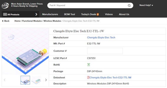
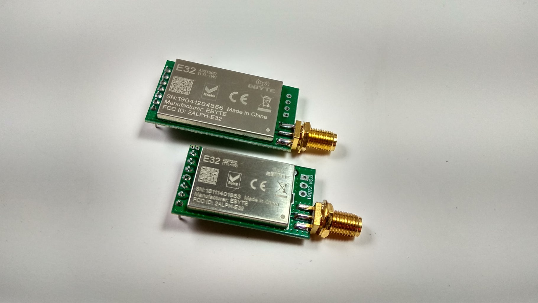

You can find the LoRa modules from eByte on the following links from LCSC:
E32 1W module LCSC: https://bit.ly/2R4xxct
E32 100mW module LCSC: https://bit.ly/2ZjbLo6
Antenna 433MHz LCSC: https://bit.ly/2WBUk5A
Firebeetle ESP32 from DFRobot: https://bit.ly/2FwJ8LM
Step 2: Get PCBs for Your Project Manufactured
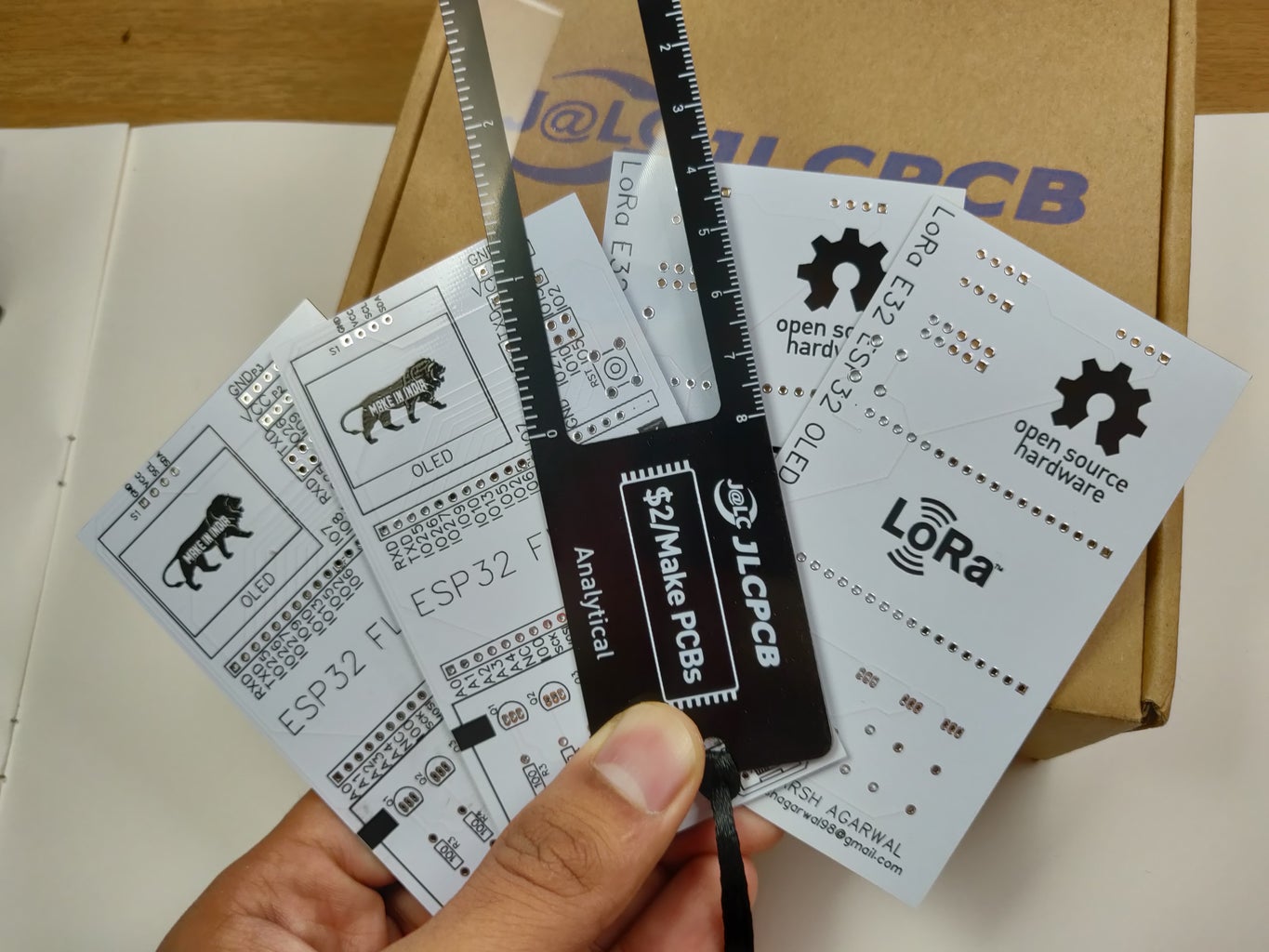
You must check out JLCPCB for ordering PCBs online for cheap!
You get 10 good quality PCBs manufactured and shipped to your doorstep for 2$ and some shipping. You will also get a discount on shipping on your first order. To design your own PCB head over to easyEDA, once that is done upload your Gerber files onto JLCPCB to get them manufactured with good quality and quick turnaround time.
Step 3: Previous Tutorial [OPTIONAL]
I made a getting started tutorial video for the same module last week which I recommend that you should take a look before progressing with this tutorial.
Step 4: Wiring and Circuit
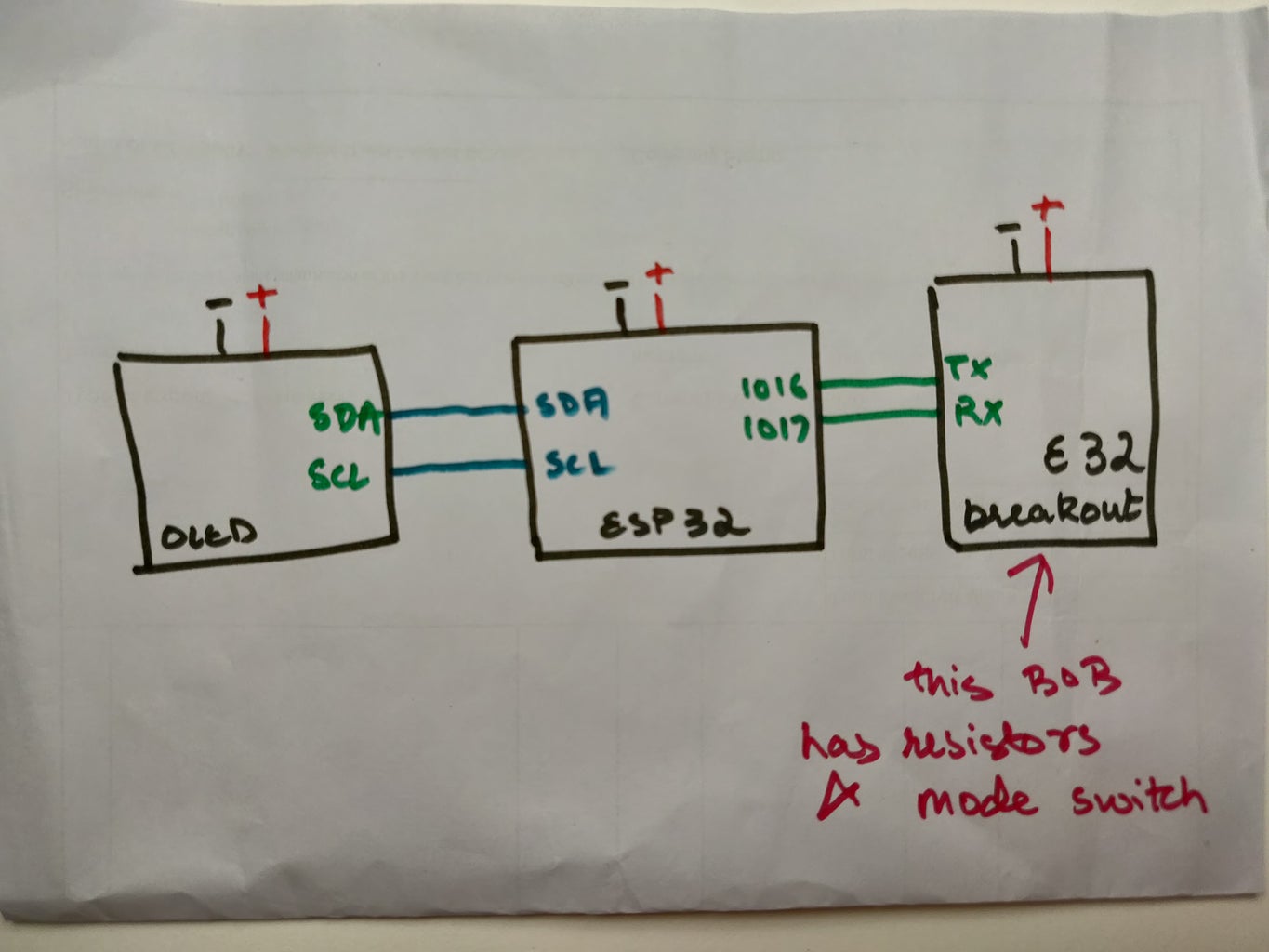

All the connections are done already on the PCB.
Connections between the ESP32, OLED and E32 breakout board are basic and connected using a couple of wires only.
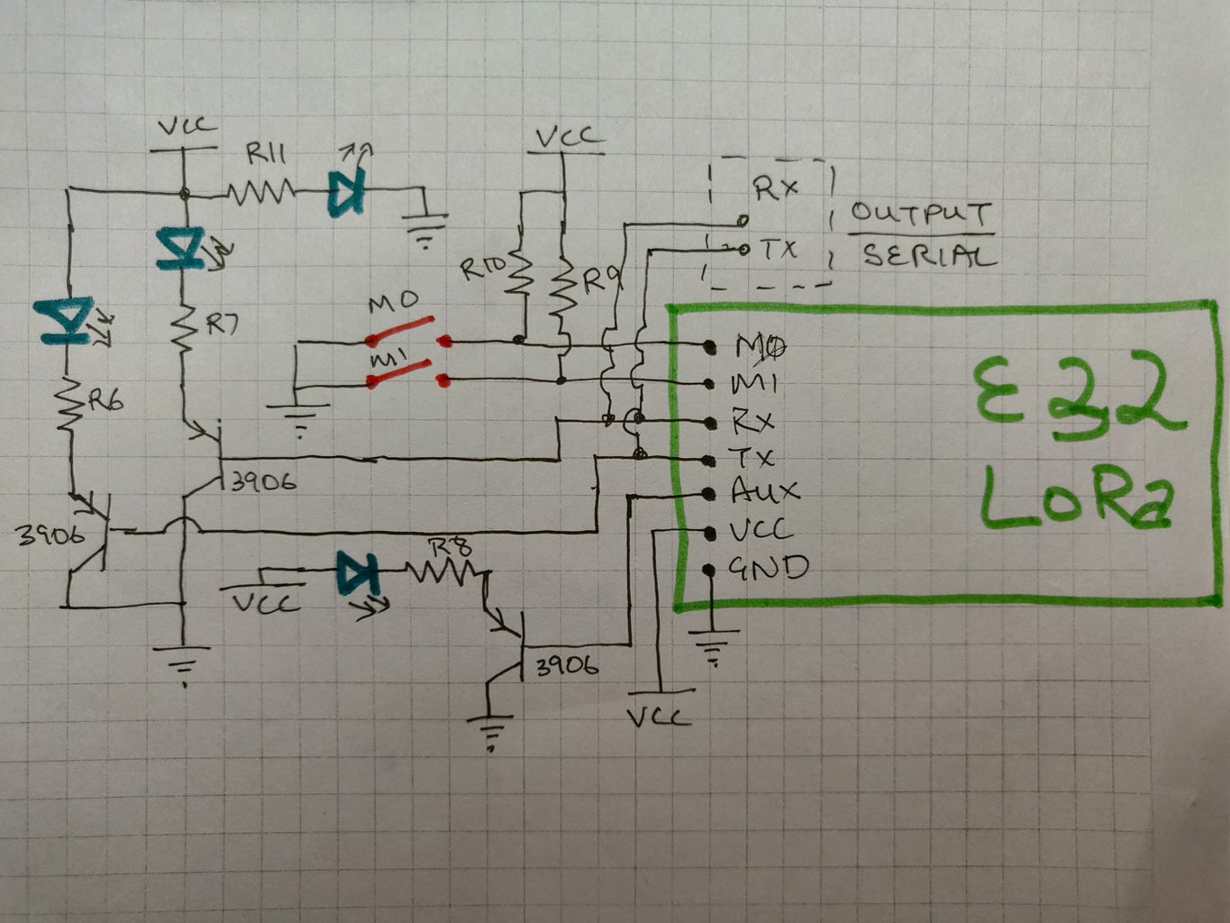
The internal connections of the E32 breakout board are a little bit more complex for which I have added a separate circuit diagram.
The most important connection to be made is of the M1 and M0 pins. They need to be connected to either GND or VCC for the operation of the module and cannot be left floating. We will learn more about the different mode selection using M1 and M0 in the next step.
Lastly, I have also attached a couple of LEDs on the Rx and Tx pins so that when data transmission is happening over UART it's visible on the LEDs.
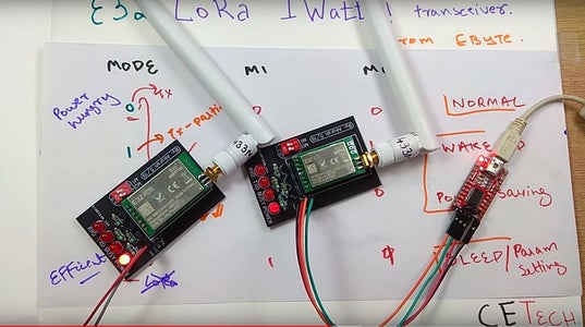
Step 5: Operating Modes

Changing the voltage of the pins M1 and M0 different modes of the module can be set.
We can see the different modes on the above table.
I mostly focus on the Mode 0 and Mode 3. For normal LoRa use, I keep the module on Mode 0 and for configuration, I keep it on Mode 3.
For this project, we will keep both the pins to 0, i.e Mode 0.
Step 6: Our PCB
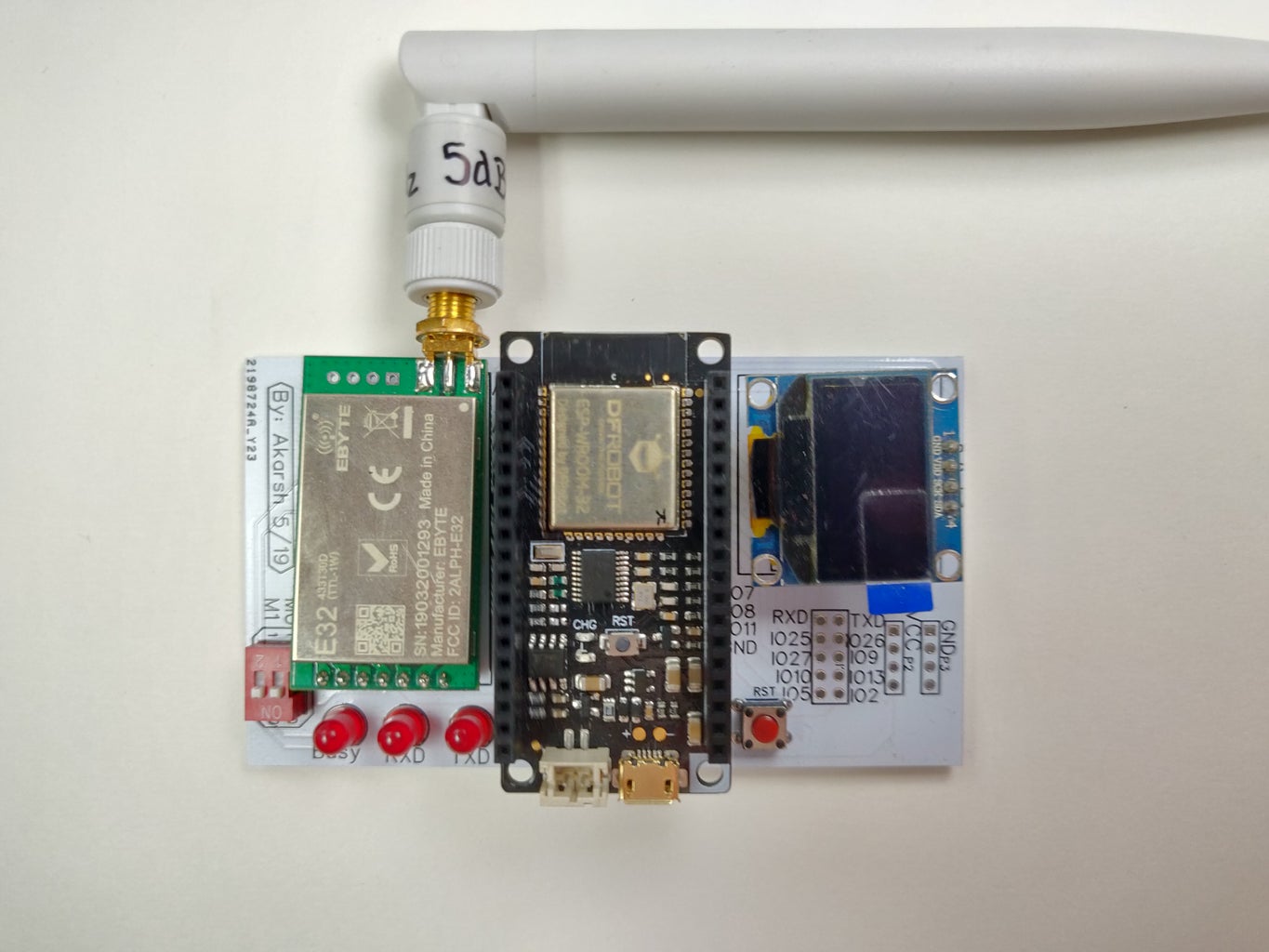
I designed a PCB using the above circuit diagram and got it manufactured.
The PCB has headers for the ESP32, E32 and OLED display modules.
There are also some basic components apart from that.
I have also broken out some extra GPIO pins of the ESP32 on the PCB for the possibility of expansion of the project.
So I soldered the components on the PCB and programmed the ESP32 in the next step.
Step 7: Coding

1. Download the GitHub repository: https://github.com/akarsh98/ESP32-with-E32-LoRa-mo...
2. Extract the downloaded repository.
3. Open the raw sketch in the Arduino IDE.
4. Navigate to Tools > Board. Select the appropriate board that you are using, Firebeetle ESP32 in my case.
5. Select the correct comm. port by going to Tools > Port.
6. Hit the upload button.
7. When the tab says Done Uploading you will see the OLED display spring up to life.
Step 8: Final Test
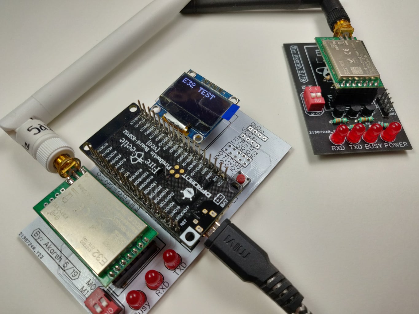
I connected the ESP32 PCB to power using micro USB.
For the other side of the LoRa link, I used the breakout module from the previous tutorial which I connected using an FTDI module to a PC and set the mode switch of M0 and M1 to 0 & 0.
Then started sending data over UART to the module connected to the PC and observed that the OLED started showing the data received over LoRa after that ESP32 sends an acknowledgement message back which we see on the serial monitor. Watch my video for the same demo.


