

Introduction: ESP8266-07 Programmer With Arduino Nano


This is a short tutorial for creating a nifty ESP8266-07/12E programming board using an Arduino nano. The wiring schematic is very similar to the one demonstrated here. You have the options to wire this project onto a breadboard, solder yourself a perfboard, or use the gerber files attached to create a more reliable pcb. I suggest sticking with a pcb or perfboard (if you trust yourself to solder properly) if you often program the mentioned devices.
I am planning to create some content with the ESP-07, and I will be using the board created in this tutorial regularly.
The design has an on-board 3.3v voltage regulator that turns on the ESP module, you’d have to connect a 5v supply in addition to the Arduino usb cable. Moreover, you should also use a breakout board; it makes everything easier to work with.
Supplies
- Arduino nano
- ESP8266-07 or/12/e
- ESP-07 breakout board
- Mini usb cable
- 5.5mm power jack (male and female)
- Female header pins 1*15 (2pcs)
- Female header pins 1*8 (2pcs)
- 6pin toggle switch (optional)
- push buttons (2pcs)
- 5Kohm resistors (2pcs)
- 10Kohm resistors (2pcs)
- lm1117 3.3v (I used the smd version, you can use TH if you wish to create a breadboard circuit)
- 47uf capacitor (you can use higher values if you experience power issues)
- breadboard, or perfboard, or pcb
Step 1: The Wiring
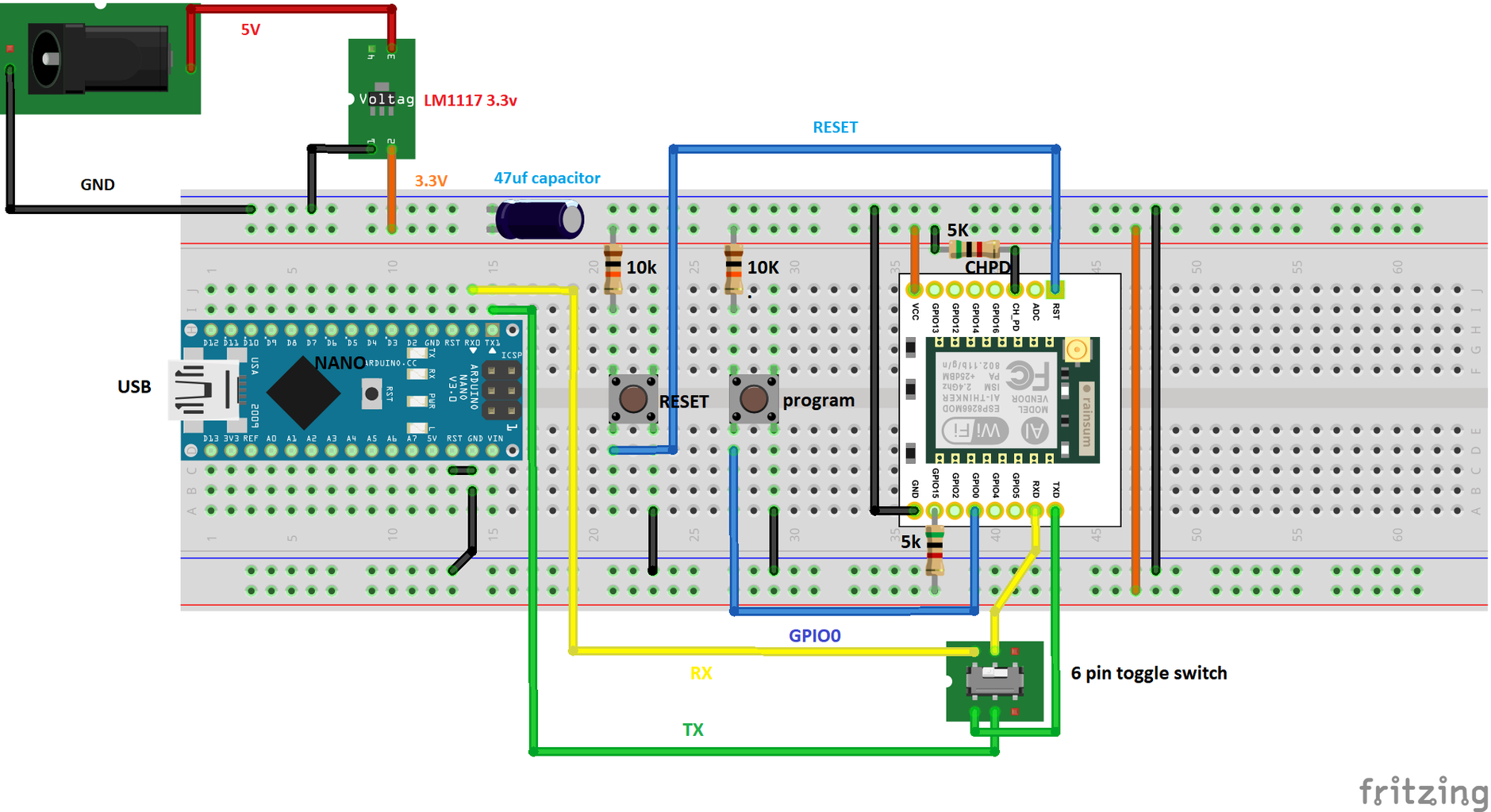

Breadboard circuit:
1. Plug into a breadboard the Arduino nano, and the ESP module using the breakout board. For better access to the pins of the breakout board, you can use two breadboards instead of one as shown.
2. Powering the rails: connect the 5v pin of the power jack to pin 3 of the lm1117 3.3v regulator, GND to pin 1, and the output from pin 2 to the "+" rail of the breadboard. Also connect the GND pin of the power jack to the "–" of the breadboard. Add a 47uf capacitor and connect the rails together as shown.
3. Add two push buttons (reset and program) and connect one pin from each to reset and another to GPIO0 of the ESP. Pull up the normally connected pins to 3.3v using 10kohm resistors. Connect the normally open pins to GND
4. Connect + rail to VCC of ESP breakout board
5. Connect – rail to GND of ESP breakout board
6. Pull up pins CH_PD and GPIO15 of ESP to +3.3v rail using a 5kohm resistors
7. Connect the RX pin of the nano to the RX of the ESP using a 2-channel toggle switch
8. Connect the TX of the Nano to the TX of the ESP using the 2-channel toggle switch. (the toggle switch is optional; it makes it possible to completely disconnect the signal between the Arduino and the ESP)
9. Bridge the RST and GND pins of the Arduino, this step "disables" the ATmega chip.
I used an external 5v power supply because the arduino cannot deliver enough current to power the ESP module reliably. I am using an old charger and a modified usb cable.
Step 2: Soldering a Perfboard Circuit


I have made a layout for a single sided 7cm by 9cm perfboard based on the wiring diagram in the previous step. Try to use the exact same component location so you don't run into routing issues. You can use the attached fritzing images as guides.
Also, I have used 2.54mm female header pins to make the Nano and the ESP detachable.
Step 3: PCB Circuit

Send the attached gerber to a pcb manufacturer and that's it!
It is based on the wiring previously mentioned, but the layout is a bit different. I had to make it more compact to save you money
The files were created with EasyEDA.

Step 4: Adding Esp8266 Support to Arduino IDE


You can skip this step if you have the module already configured!
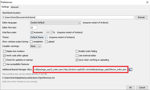
Step 1: open the IDE and go to File>>preferences, a window pops up. It will look like one of the attached images
Step 2: In the red box, paste this line:
http://arduino.esp8266.com/stable/package_esp8266com_index.json
if there is something already written there, add a comma and then paste the URL
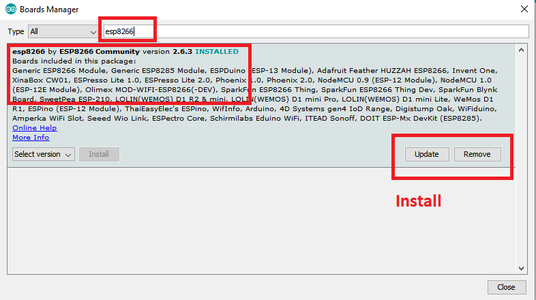
Step 3: Go to tools>>board>>board manager, refer to the attach images if you have any problem with that
Step 4: when the window finishes loading, use the search box to search for esp8266, find the result with the title "esp8266 by esp8266 community" and install
NOTE: I installed version 2.5.2 because some later versions are causing "fatalerrors"
Step 5: When installation is complete, go to Tools>>Board>> find and select "generic esp8266 module"
Step 6: Go to tools and under "board: Generic esp8266 module" you will find some configurations. Make sure that yours match those in the attached image.
Step 5: Uploading a Sketch
Plug a usb cable to the Arduino Nano and connect it to a computer. Also, hookup a 5v power supply to the power jack on the board.
If you have decided to add a toggle switch, make sure that it is pressed.
To put the esp module into programming mode:
Press and hold the RESET and PROGRAM buttons, and then relese "RESET" while still pressing "PROGRAM"
Hold for a moment and then relese the "PROGRAM" button.
On the computer, open the IDE and go to Tools>>port and select the COM port where you have connected your usb cable into the computer.
Write your code, and use the upload button on the top left of your IDE to start programming the ESP module.
Step 6: Test the Code
It is possible to test some programs without removing the module from its socket.
To do so, unpress the toggle switch, and hit the RESET button.
I have added the toggle switch to isolate the two boards completely
ENJOY!


