Introduction: ESP8266-12E DHT Thermostat
About a month ago I woke up to find that I had no flowing water, the pipes had frozen in my pump house. It's been a cold winter. The little temperature controlled power block in my pump house had failed, tripping the circuit breaker. Consequentially, the heat lamp used to warm the pipes did not turn on. After 8 hours of pipe warming with a space heater I finally had water flowing and there were no breaks, whew! With the thermostatic power block fried, I would have to leave the 250 WATT heat lamp on 24x7. Not ideal for my power bill.
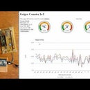
So, I decided to build my own thermostat switch using an ESP8266-12E and a DHT (Digital Humidity Temperature) sensor. The ESP8266-12E reads the DHT sensor data to obtain temperature and humidity values. A relay switch is turned On/Off based on the temperature value. The thermostat settings can be controlled by accessing the ESP8266 web server using any standard browser. The web interface uses form inputs to control temperature thresholds used to turn the relay switch off/on. The web interface also has inputs to control the time interval used to read the DHT sensor. The readings are stored in a data file and displayed on a web page using Google Charts.
I modified an extension cord and attached it to the relay switch. I plugged the heat lamp into the extension cord and installed it in my pump house. It's been working great for about a month now and I no longer have to go outside to verify that the thermostat is functioning. Now I just check the web page!
Step 1: Things You Need
To do this build you will need a few things:
Hardware
- An ESP8266-12E board (availble online for less than $10)
- A DHT22 sensor (online for $10)
- A relay switch. This project uses the "Uxcell DC 3V Coil 5 Pins SPST Power Relay JQC-3F" (bag of 10 less than $10)
- A NPN transistor. This project uses a 2N3904 (cheap)
- Jumper wires. Male - male. (Less than $5 for more than enough for this project)
- Breadboard. One regular or two small ones (Less than $5 from Amazon or eBay)
- 1 LED and a resistor
- Printed circuit board - (bag of 50 pieces for about $10 online)
- A 2 Pole Terminal Block. This project uses a "2 Pole 5mm Pitch PCB Mount Screw Terminal Block 8A 250V" (30 for less than $5)
- 16 pin headers. This project uses "Gikfun Single Row 16 pins Female Header for Arduino EK1417" (50 for less than $20)
Software
- You will need to download the source code sketch and libraries here: https://github.com/dmainmon/ESP8266-12E-DHT-Therm...
- You will need the Arduino IDE to compile the souce code sketch. Available from http://www.arduino.cc/
Step 2: Breadboard Wiring
Before uploading the source code sketch and definitely before doing any soldering, build a breadboard version. A breadboard version will help you become familiar with the wiring without committing to soldering a circuit board. These two images above offer a 3 volt power option and a 5 volt power option. The 3 volt wiring diagram uses the 3.3v power supplied by the ESP8266 when connected via USB. The 5 volt option bypasses the ESP as a power source. The hardwired version actually uses a hybrid; it's the same as the 5 volt option except the DHT is powered from the 3.3v ESP power source.
Step 3: Arduino IDE Setup and Source Code
Now let's connect the ESP8266 to a computer via the USB port and open the Arduino IDE.
Since we aren't using an Arduino UNO, MEGA or other hybrid, we need to make some changes to the IDE before it will communicate with the ESP8266 board. The video above will help get you connected!
Now you are ready to upload the source code downloaded earlier. Make sure you copy the libraries from the download into the Arduino libraries folder. This is usually \Documents\Arduino\Libraries\ on a windows pc.
The video below provides an overview of the source code as well as a demonstration of the web interface.
Step 4: Create a Soldered Circuit Board Version
Hopefully these images and the experience of building a breadboard version will help you build the circuit board version. I like to use headers so I can plug the ESP8266-12E board in and remove it if necessary. I also use a separate USB input connector for 5 volt power input (instead of connecting the USB directly to the ESP8266 board). I did this so I could operate the relay switch at 5 volts rather than 3 volts. I used a 3 volt relay but this way a 5 volt relay could also be used.
I also use A 2 Pole Terminal Block to connect the switched power. In my case, I have an extension cord connected to the terminals. I cut the "hot" wire of the extension cord and connected the two ends into the terminal. So in this case the switched power is 110 V/AC. The same relay could also be used to control DC voltage.
Step 5: Tips and Tricks
This video demonstrates a breadboard version. There are also some tips and tricks that will help if you decide to build the soldered circuit version. Includes a helpful tip on using hot glue to seal and insulate the back of your soldered circuit.
Let me know if you have any questions.
Good luck on the build!

Participated in the
Microcontroller Contest 2017

Participated in the
Sensors Contest 2017


