

Introduction: ESP8266 Breadboard


Make your cheap ESP8266 module breadboard compatible without an expensive adaptor.
All that is required is your ESP, a small piece of perf board, header pins, small wire and a capacitor.
This Instructable will lead into another project I plan to write up shortly: an ESP based artnet node.
Step 1: Perf Board Prep

Cut your perf board so it's 8 holes wide. I made mine longer than required as I planned to add a couple of tac switches for reset and programming.
Solder your header pins on. I chose 14 pins as I don't see the point in breaking CH_PD or pin 15 out. It's easiest to insert them into the breadboard while soldering to ensure they're straight.
Step 2: Wire ESP


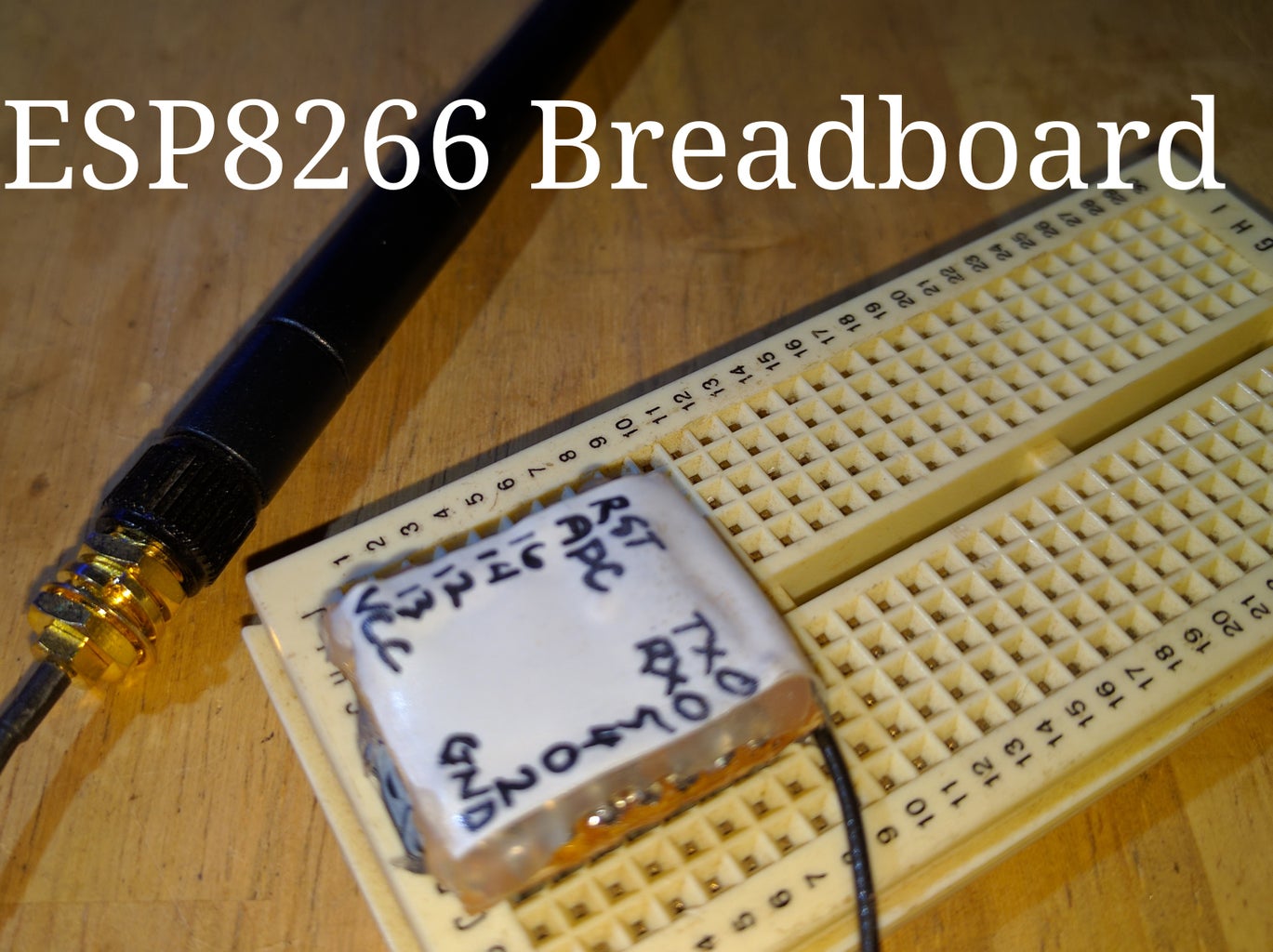
I am using the ESP8266-07 which has an external aerial. This gives better range (especially when in a case) over the versions with a trace antenna.
Note that i have the ESP labels facing away from the perf board. This means i can read them later. I also decided to put it on the underside of the perf board to allow easier soldering. It still fits perfectly into the bread board and a side benefit is that the on board LEDs shine through the white label so are still visible.
Add a short piece of wire to each of the ESP pins. I used magnet wire. Check your connections with a multimeter.
The next 2 connections are required for normal operation on the ESP 07 module. Check what connections you'll need if you have a different version of ESP8266.
Wire CH_PD directly to VCC. I did this across the bottom of the ESP.
Wire pin 15 to GND via a 1k resistor. I used an smd resistor so I could fit it under the perf board. The pins are right next to each other so this is the easiest option. I forgot to take a photo before gluing it all together.
Now poke all the wires through the perf board. Each wire should go through the hole next to the header pin it will be attached to.
Put a small amount of hot glue on the perf board and sandwich everything together. It should just got between the header pins. ensure there are no shorts between ESP pins and the header pins.
Step 3: Wire Perf Board


I'd recommend doing most of this step with the header pins inserted into a bread board.
Wire each ESP pin to the correct header pin. Check continuity.
Wire a capacitor between VCC and GND to ensure a stable power supply. I tucked mine under the end of the ESP and added a dab of hot glue for good measure.
I planned to add tac switches for reset and programming but I didn't have any on hand. I would recommend you do add them... it's quite annoying not having them and I regret not heading down the road to grab a couple for this.
Cut your perf board to the length you'd like at the point during this step that works for you. I did it just before I attached my capacitor.
Step 4: Test and Label


This step assumes you are using the Arduino Core for ESP8266. I'd highly recommend it as you don't need a separate microcontroller for most small projects.
Check it out here: https://github.com/esp8266/arduino
You'll find all the instructions to get your Arduino IDE setup.
Connect your USB to TTL to the ESP and power. Remember it's 3.3V not 5V. There are countless tutorials on how to do this if you are unsure.
As you can see in the photos, I use my Arduino Mega for programming. Simply tie the mega's reset to GND, wire the TX to ESP TX, and wire the RX together through a voltage divider to ensure it is below the 3.3V the ESP can handle. Note they run off different power supplies... don't feed 5V into your ESP.
Check you can program to ESP and that each pin works. I made a small sketch which flashes an led on each pin on then off in sequence. I didn't test any of the input as I was being impatient. I figure that if the output function of a pin works, the input should also.
Make a label for the top side so you know what each pin is. I used white electrical tape and a sharp pointed marker.
Smother the board with hot glue to hold the header pins in place a bit better and quickly put your label in place before it sets. Give it a bit of a squeeze to smooth the glue out so it looks nice and flat.

Participated in the
Circuits Contest 2016


