

Introduction: ESP8266 LCD Billboard


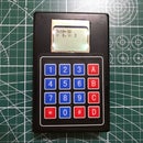

Always wanted some automatic LCD billboard that shows your choice information? This project will let you build a IoT billboard and write your own text on the board, from a webpage.
In this instructable I'll provide you the following building blocks for ESP8266 projects:
- How to build your own ESP-12 board
- How to pass serial data between the ESP-12 and the Arduino (Uno or Mega)
- How to provide power to both board from a single source
My initial goal was to connect an arduino to the web using the most simple, available and affordable device. By simple I mean minimum wires (at an expense of communication rate) and as much as documented. I tried two other devices:
- Ethernet shield - downside that it requires proximity to a LAN wall socket.
- CC3000 shield - expensive (about 30$)
Another thing to note is that both devices require use of AT commands, which are not easy and fast to learn. After a while I decided to search for another simple solution with 2 wire communication that can connect to the internet and the arduino can operate it. So I found out of ESP8266 chip series: ESP-01, ESP-07, etc. I decided to buy the latest and greatest: ESP-12.
Note: this instructable is still under edit (09-November-2015). I plan to finish it soon
Step 1: ESP8266 ESP-12 Chips

Many variants exist with same or similar names for the ESP8266 chips. I also have a nodemcu devkit 1.0 board and the chip on it looks exactly the same like my ESP-12 with the extra IO pins at the bottom. That ESP-12 variant is generally marked ESP-12E. Although my chip has ESP-12-Q written over it, I think it is the same.
You can verify it by running node.info() command. Here is a comparison of node.info() of my nodemcu devkit and the chip I have:
> =node.info()
0 9 6 392866 1458400 4096 2 40000000
> =node.info()
> 0 9 6 372301 1458400 4096 2 40000000
The only difference is the chip id field, it is a unique identifier of every ESP8266 device.
Step 2: Useful Resources
Before we start, here are some useful links that helped me a lot:
- LuaLoader: It is a simple terminal with shortcuts for some useful commands.
- Lua Demo: Test your lua code before uploading to the ESP-12. It can save you a lot of time for tweaking the code.
- Lua Languange reference: Good source for learning the basics of this language.
- HTML Forms: If you want to build a webpage that sends data, you must know some basic HTML forms.
- Good blog about ESP-12
- Scargill blog
Step 3: Bill of Materials
To create this project we will need the following components:
- Arduino Mega 2560
- TFT LCD
You can use Arduino Uno and a smaller screen, or use without the screen and just take the communication part from my sketch.
For the ESP8266 board we will need:
- ESP-12
- Voltage regulator for 3V (lm1117)
- Capacitors (2 of 10uF)
- Resistors (2 of 10kOhm)
- Logic level transistor (IRL540 MOSFET)
- Wires
- Jumpers
The voltage regulator is to convert the 5V supply from the Arduino to the 3.3V required by the ESP-12 (I know that I could have used the 3.3V supply of the Arduino, but I think that the 5V is more stable).
The Logic level transistor and the two resistors are to convert the 5V logic levels of the Arduino to 3.3 logic levels of the ESP-12. If you have a module that does that, you can use it instead. They cost less than 0.5$.
Step 4: Logic Level Transistor

One word off-topic about logic level transistors. These transistors are very useful to switch or PWM some other high power device from a micro-controller pin. The MOSFET is a switch that opens if the gate voltage is above some threshold. The switch is open in a sense that the transistor lets current flow between the drain and the source. In the datasheets this voltage is defined as VGS(th). Current starts to flow when your VGS is above VGS(th). But if we want a full opening of the switch, we must look at the datasheet (always look at the datasheet).
I added excerpts of the datasheets of IRF540N and IRL540N (L for logic). One can see that although VGS(th) is 4V for the IRL540N (and the Arduino outputs 5V at HIGH so one might think it is enough), it will fully open only at about 7.5V. It can still work on low current projects.
This is not the only Logic level transistor, there are many others, including BJTs. Use whatever available.
Attachments

Step 5: Wiring Scheme


The scheme has several main parts:
- Power supply: the lm1117 and the capacitors
- Logic level conversion
- Jumpers for the ESP8266 (GPIO0 between Vcc, for normal operation, or to GND, to flash the firmware)
For the logic level conversion I didn't have a module, so I made one using one MOSFET transistor and two resistors. I assume that the modules you buy from aliexpress are built the same way. It is bidirectional: every pin can be output or input. The circuit can be found here: Logic level shifter. I added it in the schematics of this step.
Note 1: I put the logic converter only for the TX wire from Arduino to the ESP8266, because it is forbidden and dangerous to drive high voltage on the latter one. But for the wire from the ESP8266 to the Arduino I didn't assemble a logic level converter transistor. Instead, the wire goes directly from the TX pin on the ESP-12 to the RX of the Arduino. It works because V_In_High (the lowest input voltage to be considered "1") is 3V in the Arduino, so 3.3V that goes out of the ESP-12 is just enough. To be on the safe side for high data rates I would put another converter.
Note 2: In some tutorial about the ESP-12 it was mentioned that you must pull up the GPIO2 pin. I did that but nothing functioned. When I accidentally left GPIO2 disconnected - the device started working normally. I guess that there are many variants by the name ESP-12.
Note 3: I didn't put a DC power jack because the devices will be powered from the Arduino. If you want to make a nodemcu board, you can add a power jack and an FTDI UART device (like in this tutorial).
Note 4: EN pin is sometimes called CH_PD. It is the same pin.
Note 5: To power everything from a single power supply I soldered Vin pin on the Arduino and connected it to Vcc pin on the ESP8266 PCB board pin.
Step 6: PCB Layout
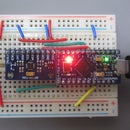
After testing that everything works on a breadboard I placed on the components on a 4x6 breadboard. All the inputs (5V, GND, RX, TX) were placed on one side. All the wiring were made on the bottom part of the PCB, so that the upper part will contain only components.
Step 7: Flashing the Firmware
Before flashing the firmware you first must load in the Arduino this simple program that duplicates all the data in the USB serial port to the modemcu serial port. If you use Arduino Uno you can do this by software serial.
#include <SoftwareSerial.h>
#define baudrate 57600
mySerial(10, 11); // RX, TX
void setup() {
// Open serial communications and wait for port to open:
Serial.begin(baudrate);
while (!Serial) {
; // wait for serial port to connect. Needed for native USB port only
}
// set the data rate for the SoftwareSerial port
mySerial.begin(baudrate);
mySerial.println("Hello, world?");
}
void loop() {
if (mySerial.available()) {
Serial.write(mySerial.read()); }
if (Serial.available()) {
mySerial.write(Serial.read()); }
}
If you have an FTDI or CP2102 usb to serial you can use them instead.
If you use Arduino Mega, it has 3 more hardware serial ports you can use. I use Serial1 in pins 18, 19 (you just need to replace "mySerial" by "Serial1" and remove the SoftwareSerial inlcude).
To flash the firmware put the GPIO0 jumper to GND, and follow the instructions on this site: benlo.
Note 1: I downloaded the floating point firmware.
Note 2: To flash the firmware you must configure 4 "files" in the ESP8266Flasher Utility. The first one is the new firmware you downloaded, the others are different areas in the chip memory.
Note 3: The ESP-12 comes with AT firmware. You can use it if you want instead of flashing nodemcu. In this case the Arduino will control the ESP-12. It adds overhead to the Arduino, but simplifies your project: all the code is in one place.
Step 8: Serial Communication Between Arduino and ESP-12
We already have the Aruino and ESP-12 communicating (the data you see in the terminal is the re-transmission of the Arduino). Now we want the Arduino to perform some action after receiving predefined commands from the ESP-12.
Transfer data from the ESP8266 to the Arduino
The first thing we want to do is to pass some 2 byte integers from the ESP-12 to the Arduino. I demonstrate it with 2 byte integers but it can be 4 byte long integers or even 4 byte floats, the procedure is the same.
| Start Byte, | Byte 0, | ..., | Byte N-1 |
|---|
We send a start byte first, then we send N bytes of data. N is pre-defined. When the Arduino receives the start byte it stops printing the data to the serial port and instead it puts the received byte inside a buffer. After that, it assembles the data: every 2 bytes are an integer. Note that the start byte should not be a printable byte, because then the receive mode can be accidentally invoked. To make it better for data reliable, you can add a checksum field over the data. I defined the following commands:
| Command Name | Code |
|---|---|
| FETCH_DATA_COMMAND | 0x80 |
| PRINT_DATA_COMMAND | 0x81 |
| PRINT_DATA_LCD | 0x82 |
When code 0x80 is received, the following data is sent by the ESP8266:
uart.write(0,bit.arshift(bit.band(x,0xff00),8), bit.band(x,0x00ff))
The Arduino puts the two bytes together again:
get_x = (data_arr[0] << 8) + data_arr[1];
Print data from the ESP8266 to the Arduino
I defined another command that directly prints data from the ESP8266 to the LCD. I can add more options like selecting a font or printing lines etc. But I plan that the Arduino will do most of the printing job and the ESP8266 will only fill in numbers and text from the internet.
Step 9: Web-Server Control
To control the Arduino you can run a telnet server and parse the user input, or you can run an HTTP server with buttons, radio etc. For better user experience I chose the second option. This is not a tutorial about HTML, so I'll say shortly that you create a form and send data to the server with POST or GET method. Then you go over the parameters you received in the ESP-12. I preferred using GET because of ease of debug (all parameters are in the URL).
Some of the variables I pass in GET are optional. There is no isset() function like in php, and I had a problem that nil parameters sometimes were non-nil. I used pcall() (something like try-catch) to test if they are nil but it wasn't enough in all cases, so I added a double check if variable is nil.
Step 10: Complete Source Code
Change the password and SSID for your home network in the init.lua file.

