

Introduction: Easy DC Motor Controller


If you're building a robot or other microcontrolled gadget, you will need to drive DC motors forwards and backwards. In this instructable, I'll demonstrate a simple and inexpensive circuit that controls a DC motor from two I/O pins. It requires no integrated circuits, and uses commonly available parts. I recommend you build it on a breadboard the first time. I designed this circuit, but I'm not the inventor of this type of motor controller. I got interested in motor control circuits like this one when I saw the amazingly precise movements of the Makerbots and CNC routers at Maker Works in Ann Arbor.
Step 1: Parts List

Here are the parts you'll need. All of them should be available at your local RadioShack or hobby store.
(1) DC motor
(4) MOSFET transistors. I used the IRF540N, but any N-channel MOSFET will do.
(4) Diodes
(2) NPN bipolar transistors. I used the BC548.
(2) PNP bipolar transistors. I used the BC327.
(4) 2200 ohm resistors (red-red-red)
(4) 10K ohm resistors (brown-black-orange)
Some jumper wires and a breadboard, if desired
The resistor values are not critical. Values that are fairly close will most likely work fine.
Step 2: The Finished Circuit
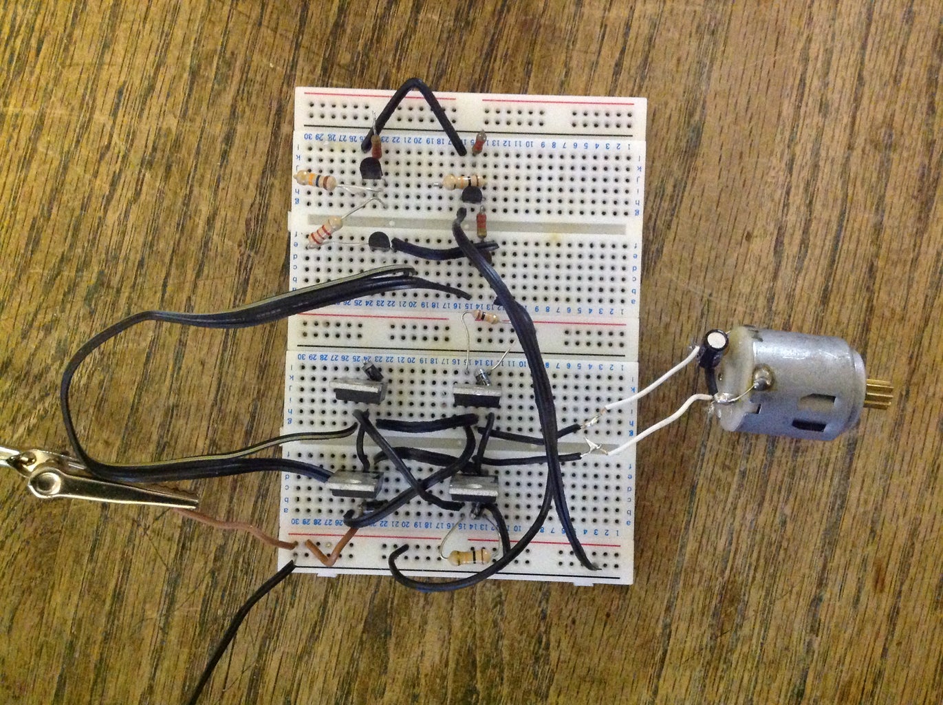
Here's a picture of the complete circuit on a breadboard, with some additional part labels.
Step 3: How to Use It
I'm connecting the transistor gates to positive by touching them with a jumper wire in this video, but they also are easily switched by two microcontroller I/O pins. I put a piece of red tape on the motor shaft to make it easier to see.
Step 4: How It Works

When you set pin one high with your microcontroller, the NPN transistor Q7 switches on. This connects the base of the PNP transistor Q5 to ground, turning it on as well. Q5 then connects +12 volts to the mosfets Q1 and Q4, which connect the motor to positive and ground. Setting pin 2 high connects the motor to positive and ground in the opposite polarity. The four diodes protect your transistors from voltage surges that sometimes occur when a DC motor is abruptly stopped. The 10K ohm resistors pull the bases of the transistors to ground when your I/O pin goes low, and the 2200 ohm resistors limit the current that can be drawn from your I/O pins to protect them. Have fun spinning motors! I used two of this circuit for the drive train of my robot butler.

Participated in the
Kit Contest


