

Introduction: Electronic Safe With Arduino


Hello, and welcome to my latest project! In this tutorial I will teach you how to make a fully functional safe with an Arduino Uno!
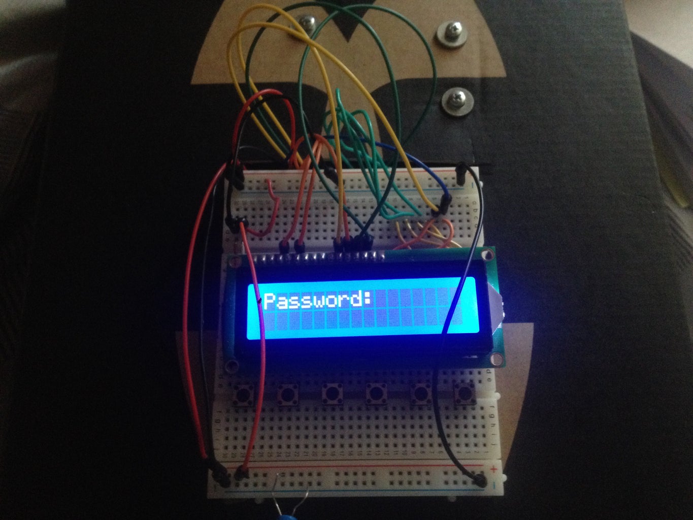
This project includes a 6 digit password (123142), that must be entered if you want to unlock the safe. There are 4 buttons to submit characters(1, 2, 3, or 4), an enter button, and a clear screen/lock button. When the safe is unlocked, it will remain unlocked until the button to lock it is pressed.
The locking mechanism is simple - a servo motor is mounted to the shoebox, and a slit is cut in the shoebox and the door flap. When in the locked position, the motor is turned in between the openings, making it not possible to open.
If you choose to build this, everything you need to know is in here! Let's get started, shall we?
Step 1: Parts List

Electronic Parts List:
- Jumper Wires(30)
- 220 OHM resistor(1)
- 16x2 LCD Screen(1)
- Push Buttons(6)
- 100 uF Capacitor(1)
- Standard Servo Motor(1)
- 9V Battery & Cap(1)
- Breadboard(1)
- Arduino Uno(1)
Other Parts:
- Washer(5)
- Plastic Washer(1)
- Screw(5)
- Nut(5)
- Duct Tape
- Shoe Box(1)
- Spare Cardboard
- 3/4th inch Conduit Strap
Tools:
- Screwdriver
- Ruler
- Knife/Blade
All electronic parts can be found at sparkfun.com .
If you don't have some of these other parts, there are ways to compromise!
Step 2: The Code

I am going to share the code right away ahead of time - copy and paste this into your Arduino IDE. If you don't have the Arduino Software yet, you can download it here: https://www.arduino.cc/en/Main/Software
#include <Liquid.Crystal.h>
#include <EEPROM.h>
#include <Servo.h>
int address = 0;
static unsigned long SaveTimer;
static unsigned long SaveDelay = (30 * 1000);
char CODE[10] = "123142E"; //change password here
char Str[10];
char CodeLength = 6;
int Pos = 0;
bool Unlocked;
static unsigned long DisplayTimer;
static unsigned long DisplayDelay = 200;
LiquidCrystal lcd(12, 11, 9, 8, 7, 6);
int buttonPin1 = 2;
int buttonPin2 = 3;
int buttonPin3 = 4;
int buttonPin4 = 5;
int enterbutton = 10;
int clearlockbutton = 13;
Servo myServo;
void setup() {
myServo.attach(A1);
Lock();
int EEPROMCodeOK = true;
for (Pos = 0; Pos <= (CodeLength); Pos++) {
Str[Pos] = EEPROM.read(Pos);
if (!(strrchr("1123456789", Str[Pos]))) {
// not a valid code
EEPROMCodeOK = false;
}
}
Pos++;
Str[Pos] = EEPROM.read(Pos);
if (Str[CodeLength + 1] != 'E') EEPROMCodeOK = false;
if (EEPROMCodeOK) {
Str[CodeLength + 2] = '\0';
strncpy(CODE, Str, CodeLength + 1);
}
ClearCode();
pinMode(buttonPin1, INPUT_PULLUP);
pinMode(buttonPin2, INPUT_PULLUP);
pinMode(buttonPin3, INPUT_PULLUP);
pinMode(buttonPin4, INPUT_PULLUP);
pinMode(enterbutton, INPUT_PULLUP);
pinMode(clearlockbutton, INPUT_PULLUP);
lcd.begin(16, 2);
lcd.setCursor(0, 0);
lcd.print("Hello.");
delay(2000);
lcd.clear();
lcd.setCursor(0, 0);
lcd.print("Password:");
DisplayTimer = millis() + 200;
}
void loop() {
Lock();
Pos = constrain(Pos, 0, CodeLength);
int buttonState1 = digitalRead(buttonPin1);
int buttonState2 = digitalRead(buttonPin2);
int buttonState3 = digitalRead(buttonPin3);
int buttonState4 = digitalRead(buttonPin4);
int clButtonState = digitalRead(clearlockbutton);
int enterButtonState = digitalRead(enterbutton);
lcd.setCursor(9, 0);
if (buttonState1 == LOW) {
Str[Pos] = '1';
Pos++;
Str[Pos] = '\0';
delay(250);
while (digitalRead(buttonPin1) == LOW);
}
else if (buttonState2 == LOW) {
Str[Pos] = '2';
Pos++;
Str[Pos] = '\0';
delay(250);
while (digitalRead(buttonPin2) == LOW);
}
else if (buttonState3 == LOW) {
Str[Pos] = '3';
Pos++;
Str[Pos] = '\0';
delay(250);
while (digitalRead(buttonPin3) == LOW);
}
else if (buttonState4 == LOW) {
Str[Pos] = '4';
Pos++;
Str[Pos] = '\0';
delay(250);
while (digitalRead(buttonPin4) == LOW);
}
else if (enterButtonState == LOW) {
Str[Pos] = 'E';
Pos++;
Str[Pos] = '\0';
delay(250);
lcd.setCursor(15, 0);
lcd.print("E");
delay(400);
lcd.setCursor(15, 0);
lcd.print(" ");
while (digitalRead(buttonPin1) == LOW);
if (strcmp (Str,CODE) == 0) {
Unlocked = true;
lcd.setCursor(0, 0);
lcd.print(" Access Granted");
delay(2000);
lcd.clear();
lcd.print(" Unlocked");
}
else {
lcd.clear();
lcd.print(" Access Denied.");
delay(2000);
lcd.clear();
lcd.print("Password:");
}
while (Unlocked) {
Unlock();
if (digitalRead(clearlockbutton) == LOW) {
delay(200);
lcd.clear();
lcd.print(" Locked");
delay(2000);
lcd.clear();
Unlocked = false;
SaveTimer = millis() + 30000;
}
}
ClearCode();
}
else if (clButtonState == LOW) {
delay(500);
while (clearlockbutton == LOW);
if ((millis() - SaveTimer) > 4500) {
}
ClearCode();
}
if ( (long)( millis() - DisplayTimer ) >= 0) {
DisplayTimer += DisplayDelay;
lcd.setCursor(9, 0);
lcd.print(Str);
lcd.setCursor(15, 0);
lcd.print(" ");
if (clButtonState == LOW) {
lcd.clear();
lcd.print("Password:");
}
}
}
void ClearCode() {
Pos = 0;
Str[Pos] = '\0';
lcd.setCursor(0, 0);
lcd.print("Password:");
lcd.setCursor(0, 1);
lcd.print(" ");
}
void Unlock() {
myServo.write(117);
}
void Lock() {
myServo.write(26);
}
Step 3: Attaching the Buttons

Now, let's get building, shall we?
First, lets set up our buttons. There are 6 in this project - 4 to type in a password, 1 to enter it, and 1 to clear the screen or lock the door! Connect a wire from the GND pin on the Uno to a ground strip on your breadboard. Then, connect each button to that ground strip. After that, connect each button to PWM pins on the Uno as shown.
Step 4: Powering the LCD Screen

The next step here would be to attach the LCD Screen. Send a wire from the Uno's 5V to the positive rail on the breadboard, and then attach the pins to the ground and power rails as shown.
Step 5: Connecting LCD Screen to Arduino

Now, you need to connect the screen to the Arduino PWM pins. The LCD screen will display what you typed in with the buttons in real time.
Step 6: Connect the Servo Motor


The Servo is what will lock and unlock the safe. You have the same one as me, the wires are grouped to a three piece ribbon cable, and there are female headers on the end. You can solder male pins to them, but I chose not to for this project because I needed the wires to reach farther. So, plug in 3 jumper cables to the female pins. Send the red and black to separate power and ground rails than everything else(as shown), and the white cable to Analog Pin 1. Make sure to use a 100 uF capacitor between that power and ground rail.
Step 7: Mount Everything


Now, you have assembled the circuit and you have the code. The next step is to mount everything to the shoebox.
Attached are all the photos that you will need to build it how I did. Now, it is a matter of simple cutting and screwing.
I hope you all like this project! If you have any questions feel free to comment below!
