Introduction: FLIPT-BIT: Retro-styled Raspberry Pi Computer


This is my take on an Raspberry Pi enclosure. It's an all-in-one computer with display, keyboard, and trackpad built-in. The RPi's USB and audio ports are exposed to the back panel, and the "cartridge slots" can be removed to get access to the RPi's GPIO pins.
The design inspiration came from this gorgeous computer from the 80s.
Supplies
- base and back panels: 1/4" acrylic or polycarbonate sheeting (base and back panel)
- front and top panels: 1/8" foamed pvc sheeting
- compact usb keyboard and trackpad
- Raspberry Pi (I used a model 3+, but a 4 should work too)
- 7" TFT display and control board (widely available on eBay, comes with a control board that supports HDMI, VGA, etc).
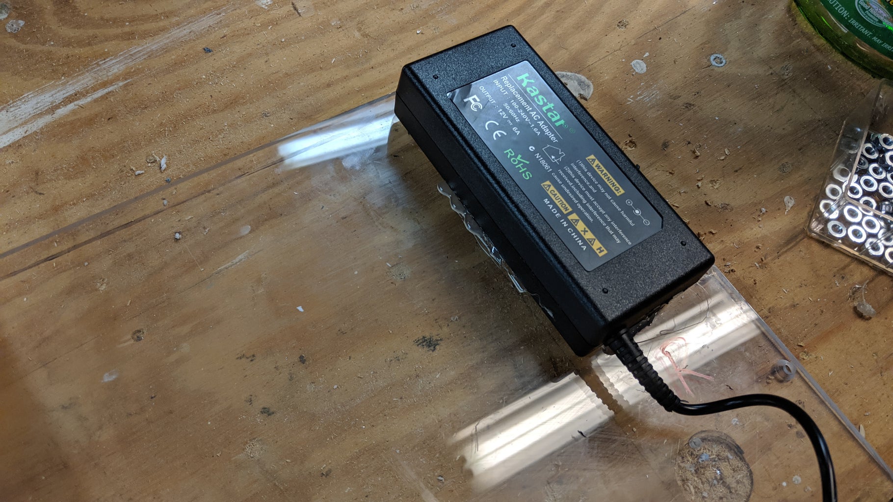
- 12v power supply, should support at least 5A (display runs on 12v)
- 12v-to-5v voltage regulator (for Raspberry Pi, keyboard, and trackpad)
- HDMI cable
- headphone extension cable, and panel-mount jack (brings an audio jack to the back panel)
- USB extension cable with panel-mount jack (brings 2 USB ports to the back panel)
Step 1: Sides and Base


The sides, being all weird angles and such, are 3D printed (STL files attached). Each side is two pieces and glued together with super glue, and has printed-in holes for #8-32 heat-set threaded inserts. The threaded inserts hold it onto the base.
The base is either 1/4" plexiglass or polycarbonate (aka Lexan) -- I can't remember which :D. Either should work -- I prefer polycarbonate as it cuts better. It's rectangular so it can be cut accurately on the table saw.


Step 2: Screen Assembly


The 7" TFT screen comes with a small breakout board with buttons for turning on and adjusting the display, selecting the input source, etc. I designed the 3D-printed frame to both hold the display in place and to to have molded buttons to make those functions usable. The pictures show how they all go together.
Note that the screen technically is loose inside the frame -- when the frame is mounted to the case it will secure the screen in place.


Step 3: Cartridge Slots
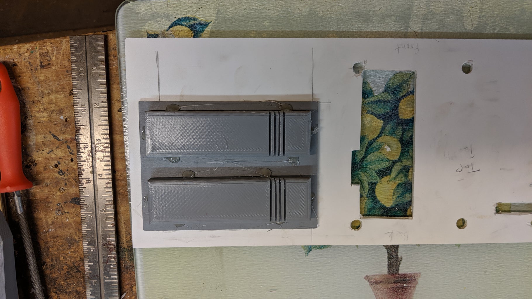
These are mostly just decorative. Print the base and two of the other pieces and glue together. (STL files are attached.) Depending on your print quality you may need to fill gaps (e.g. with wood putty or glazing/spot putty) and sand.


Step 4: Keyboard and Trackpad


Keyboard: Perixx 11486 PERIDUO-212
Trackpad: Perixx PERIPAD-501
The case is designed specifically for these parts, but should be easily modified to others.
The keyboard mounting strategy is:
- open the keyboard housing (remove the screws, then carefully crack open along the seams)
- drill screw holes in the bottom half of the keyboard housing
- mount the bottom half of the keyboard housing to wooden spacers
- reattach the top half of the keyboard to the bottom half
- mount the wooden spacers to the base plate of the computer case, using random bits of stuff to properly level the keyboard
The same strategy repeats for mounting the trackpad.
Step 5: Front and Top of Case


There are five pieces of foamed PVC here:
- large piece with holes for the screen frame and a cutout for the "cartridges"
- trim piece above the trackpad
- trim piece below the trackpad
- top "nose" piece
- bottom "nose" piece
Most were cut to width on a table saw, with any odd angles cut on a band saw.
The trickiest part of construction, by far, was getting the "nose" (the angled bit of the case in front of the keyboard/trackpad) right, so do that first. I printed templates from the sketchup file to get the angles at the ends of the nose pieces as close as possible; the width was off a bit, so adjust as necessary. From there it was just a process of sanding and tweaking until things fit.
I cut a piece of wood on the table saw angled in such a way that it reinforces the nose from inside. It's held in with hot glue; I was nervous about doing that but it worked fine. You might see in the pictures I also used finishing nails to hold the pvc board to that wood; I'd recommend NOT doing that. It was really hard to hide later.
The thin strip where the top and bottom nose pieces come together is filled with wood putty and sanded smooth. I had plenty of other wide gaps (e.g., where the nose pieces met the case sides) that also got the wood putty treatment.
The other case pieces were pretty easy, since they're rectangular. Mostly they are held on with super glue and small wood brackets. Hold off on gluing the PVC pieces until the absolute last, though, just in case you need to adjust the fit. I used lots of hot glue and blue painter's tape to hold things in place temporarily (the hot glue can be scraped off fairly easily). I printed a template from the sketchup file to locate the holes in the big top piece.
I've included my Sketchup file if you want to play with it to get dimensions, modify for different parts, etc.

Step 6: Electronic Guts


The electronics are about 95% plug-and-play:
- keyboard, trackpad, and USB extender plug into the four USB ports on the Raspberry Pi
- HDMI cable from Raspberry Pi to the displays HDMI input (on its control board)
- audio extension cable plugs into the Raspberry Pi's audio jack (get a 1/8" male-to-male audio extension cable, cut it in half, and solder a panel-mount stereo jack to the cut end).
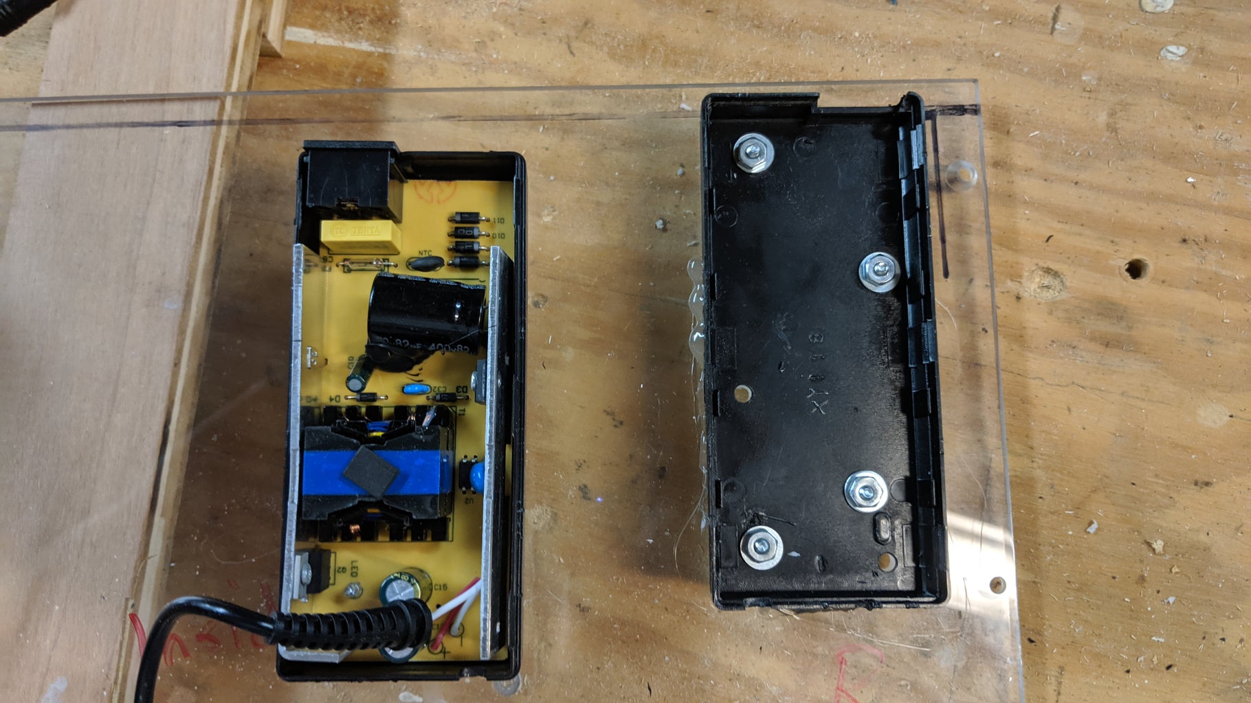
- For power distribution, cut the 12v wire coming out of the power supply and solder the switch into the break. Then pull a tap off the 12v wire and run it to the voltage regular (stepping it down to 5v) and wire the 5v end to a micro USB connector, which gets plugged into the power jack for the Raspberry Pi. (I salvaged the USB connector from a USB cable).
The 12v power supply is bolted to the bottom of the case, since plugging and unplugging the 120vac cord requires a mechanical connection. The other electronics (and the terminal block) are held in place by sticky-backed Velcro. I've used that in many of my combat robots and it works well...and it's easy. :)
The back panel is cut-and-drilled as-needed to expose the jacks, and it glued to the bottom of the case with super glue.
Step 7: Finishing


I tried several things in an attempt to get a nice smooth finish. The end result is ok, not as good as I'd hoped, but not bad either.
For filling gaps and holes in the main case, I tried standard wood filler (did ok, but not great), 2-part body filler (better, but overkill for the small cracks I had here), and glazing/spot putty (best). Then sanding smooth, primer, and glossy red.
The 3D printed parts got a coat or two (as needed) of Smooth-on XTC to smooth them out, followed by sanding, primer and flat black (except the white buttons).
And we're done!


