Introduction: FLW-M3 Surveillance Camera
Project overview
Here is just a simple guide on how to create your own "FLW-M3 surveillance camera" using an Arduino, P5.js and ML5.js.
FLW-M3 surveillance camera is an interactive installation of a security camera that actively follows passersby. This installation uses an Arduino UNO, a webcam, a servo and a red led together with Javascript libraries such as P5.js, P5 serial, and the machine learning library for artists ML5.js and specifically PoseNet.
Ultimately from this tutorial, I hope you learn how to use ML5.js together with a fysical component and many other things like serial communication! :)
Step 1: What Do We Need
The physical computing
- Arduino Uno (or another micro-controller that works)
- Servo (I use a parralax standard servo)
- Red led
- 220k resistor
- 5x electrical wires
The Javascript
- P5.js
- P5 DOM library
- P5 Serial library
- P5 serial control (a small program that handles the serial communication)
- ML5.js
The object
- MDF 4mm
- Primer spray can
- White spray paint
- Light grey spray paint
- Black spray paint
- Black sunglasses lens (or something else)
Step 2: Making Pose Estimation Work
First we are going to write the sketch that recognizes a human and places a dot on its nose. The goal is to get the horizontal X data from this point and send it to the Arduino.
Lets get started!
In this project we need a few files or libraries to make everything work:
- p5.js (you can download the complete package because this includes the DOM library)
- p5 DOM
- p5 serial port (I used the p5.serialport.js file from an example included in the package)
- ML5.js (you can include this as a link or you can download the entire library local this way you wont need an internet connection to make everything work)
Ones we have all this we can link everything in a simple HTML file:
<html>
<head>
<script src="liberaries/ml5.min.js"></script>

<script src="p5.min.js"></script>

<script src="liberaries/p5.dom.min.js"></script>

<script src="liberaries/p5.serialport.js"></script>

<script src="sketch.js"></script>

</head>

<body>
<p id="status"></p>

<p id="noseX_1"></p>
</body>

</html>
Next up is our sketch.js file where all the magic happens!
var serial;
var portName = 'COM6'; // fill in your serial port name here, you can check the right port in Arduino or P5 serial control var options = { baudrate: 19200 //baudrate has to be the same in arduino };
// this is the message that will be sent to the Arduino: var oneMessage;
let video; let poseNet; let poses = []; var noseX = [] var ifPerson = true;
//var flipHorizontal = false;
function setup() { createCanvas(640, 480); video = createCapture(VIDEO); video.size(width, height); frameRate(10);
//--------------------------------------
serial = new p5.SerialPort();
// Get a list the ports available // You should have a callback defined to see the results. See gotList, below: serial.list();
// Assuming our Arduino is connected, open the connection to it serial.open(portName, options);
// When you get a list of serial ports that are available serial.on('list', gotList);
// When you some data from the serial port serial.on('data', gotData);
//-----------------------------------------
// Create a new poseNet method with a single detection poseNet = ml5.poseNet(video, { flipHorizontal: true, detectionType: 'single' }, modelReady); // This sets up an event that fills the global variable "poses" // with an array every time new poses are detected poseNet.on('pose', function (results) { poses = results; if (results.length == 0) { ifPerson = false; } //console.log('results: ' + results); }); // Hide the video element, and just show the canvas video.hide(); }
function modelReady() { select('#status').html('Model Loaded'); }
function draw() { image(video, 0, 0, width, height);
// We can call both functions to draw all keypoints drawKeypoints();
if (ifPerson == false) { serial.write('c'); console.log("X"); ifPerson = true; } else { oneMessage = map(oneMessage, 1, 640, 65, 115); serial.write(oneMessage); console.log("browser: " + oneMessage); }
}
//---------------------------------
// Got the list of ports function gotList(thelist) { console.log("List of Serial Ports:"); // theList is an array of their names for (var i = 0; i < thelist.length; i++) { // Display in the console console.log(i + " " + thelist[i]); } }
// Called when there is data available from the serial port function gotData() { var currentString = serial.readLine(); console.log(currentString); }
//-------------------------------------
// A function to draw ellipses over the detected keypoints function drawKeypoints() { // Loop through all the poses detected for (let i = 0; i < poses.length; i++) { // For each pose detected, loop through all the keypoints for (let j = 0; j < poses[i].pose.keypoints.length; j++) { // A keypoint is an object describing a body part (like rightArm or leftShoulder) let keypoint = poses[i].pose.keypoints["0"]; noseX[i] = keypoint.position.x.toFixed(0);
oneMessage = (parseInt(noseX[0],10)); //console.log(typeof(oneMessage)); select('#noseX_1').html(noseX.toString()); //console.log(typeof(oneMessage)) // Only draw an ellipse is the pose probability is bigger than 0.2 if (keypoint.score > 0.2) { fill(255, 0, 0); noStroke(); ellipse(keypoint.position.x, keypoint.position.y, 10, 10); } } } }
And thats it! If you open the html file you will see the webcam footage with a red dot above you nose but mirrored (otherwise your servo will go away from you). You will also see the X data that gets send to the Arduino
Step 3: Using P5.serialcontrol
This is a quick one. To establish the serial communication between my sketch and the Arduino we need a middleman that handles all the serial data en sends it to one another. Previously one would use Node.js which is not that friendly to use, p5.serialcontrol fixes that. You can download p5.serialcontrol here. For windows users look at the Alpha 5 release.
Sadly p5.serialcontrol is not perfect and sometimes crashes. So be careful how much data you send.
Step 4: Everything Arduino
Next up is the Arduino code and connecting the servo and led.
#include <Servo.h>
Servo myservo;const int redPin = 12; int newval1, oldval1; int servoValue; int space = 2; int ledState = LOW; int pos = 0;
unsigned long currentMillis = 0; // stores the value of millis() in each iteration of loop() unsigned long previousServoMillis = 0; // the time when the servo was last moved unsigned long previousMillis = 0; const long interval = 500;
int servoPosition = 90; int servoSlowInterval = 60; // millisecs between servo moves int servoFastInterval = 10; int servoInterval = servoSlowInterval; // initial millisecs between servo moves int servoDegrees = 2; // amount servo moves at each step int servoMinDegrees = 45; // will be changed to negative value for movement in the other direction int servoMaxDegrees = 135;
int increment; // increment to move for each interval int updateInterval; // interval between updates unsigned long lastUpdate; // last update of position int counter = 0; bool executed = false;
void servoSweep() { if (currentMillis - previousServoMillis >= servoInterval) { previousServoMillis += servoInterval; servoPosition = servoPosition + servoDegrees; // servoDegrees might be negative
if (servoPosition <= servoMinDegrees) { // when the servo gets to its minimum position change the interval to change the speed if (servoInterval == servoSlowInterval) { servoInterval = servoSlowInterval; //servoFastInterval } else { servoInterval = servoSlowInterval; } } if ((servoPosition >= servoMaxDegrees) || (servoPosition <= servoMinDegrees)) { // if the servo is at either extreme change the sign of the degrees to make it move the other way servoDegrees = - servoDegrees; // reverse direction // and update the position to ensure it is within range servoPosition = servoPosition + servoDegrees; } // make the servo move to the next position myservo.write(servoPosition); digitalWrite(redPin, LOW); // and record the time when the move happened }
void ledBlink () { if (currentMillis - previousMillis >= interval) { previousMillis = currentMillis; if (ledState == LOW) { ledState = HIGH; } else { ledState = LOW; } digitalWrite(redPin, ledState); } }
void setup() { myservo.attach(9); // servo Serial.begin(19200); // initialize serial communication //Serial.setTimeout(10); pinMode(redPin, OUTPUT); myservo.write(90); }
void loop() { currentMillis = millis(); if (executed == false) { servoSweep(); delay(50); } }
void serialEvent () { while (Serial.available()) { newval1 = Serial.read(); //read it //Serial.println(newval1); if (newval1 > 0 && newval1 != 'c') { executed = true; ledBlink(); //if (newval1 < (oldval1 - space) || newval1 > (oldval1 + space)) { //dead band setup myservo.write(newval1); delay(15); //oldval1 = newval1; //} } if (newval1 == 'c') { executed = false; } } }
As you can see i used code that doesn't use delay() so the sweep function can be stopped at any time, that is if a person gets recognized.
After this you can test the whole system. First plug in your Arduino with the led and the servo (i placed an arrow on mine for testing), then start p5.serialcontrol and then open the html file. If it all works well, the arrow will be pointing at you at all times. if you step out of the image that the webcam captures, the servo will sweep.
Step 5: Making the Security Camera
With all this software and code out of the way lets start making something!
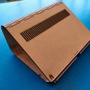
I modeled this archetype of a security camera and designed it for a lasercutter. I assembled the pieces with wood glue. Inside the camera is enough room for the Arduino, it needs some extra hole to get all the wires inside. I also placed the led in the right place and installed the black lens in front for extra security camera effect. I defused the light of the led with some plastic foil.
Next up i primed the whole thing and painted it in typical security camera colors.
Attachments
Step 6: Installation Remarks
Some last remarks about setting this installation up somewhere. The security camera itself doesn't have a camera of webcam to see the people in-front of it. What I did is hide the webcam in a pillar and placed a poster with a hole in front of it, to hide the camera, this is essential to create the right effect.
What you can also do is place the camera in a more typical position where a security camera would be, like hanging it up on the ceiling or the wall. But you can do whatever you want with it!
Step 7: The End Result
So, thats it. I hope you find this an interesting project and be sure to check out the video to see it in action!

Participated in the
Optics Contest


