

Introduction: ARDUINO : HOW TO CONNECT AND CONTROL AN LCD DISPLAYS


This instructable is the written version of my "Arduino : How to Connect and Control an LCD Displays" YouTube video that I've uploaded recently. I strongly recommend you to check it out. and Please subscribe to my YouTube channel with some more interesting video stories still waiting for you further on.
Step 1: Tutorial
The LCDs have a parallel interface, meaning that the microcontroller has to manipulate several interface pins at once to control the display. The interface consists of the following pins:
- A register select (RS) pin that controls where in the LCD's memory you're writing data to. You can select either the data register, which holds what goes on the screen, or an instruction register, which is where the LCD's controller looks for instructions on what to do next. - A Read/Write (R/W) pin that selects reading mode or writing mode - An Enable pin that enables writing to the registers - 8 data pins (D0 -D7). The states of these pins (high or low) are the bits that you're writing to a register when you write, or the values you're reading when you read. - There's also a display constrast pin (Vo), power supply pins (+5V and Gnd) and LED Backlight (Bklt+ and BKlt-) pins that you can use to power the LCD, control the display contrast, and turn on and off the LED backlight, respectively.
Step 2: Hardware Required

Arduino or Genuino Board
- LCD Screen (compatible with Hitachi HD44780 driver)
- Pin headers to solder to the LCD display pins
- 10k ohm potentiometer
- 220 ohm resistor
- hook-up wires
- Breadboard
Step 3: Circuit & Connections

Before wiring the LCD screen to your Arduino or Genuino board we suggest to solder a pin header strip to the 14 (or 16) pin count connector of the LCD screen.
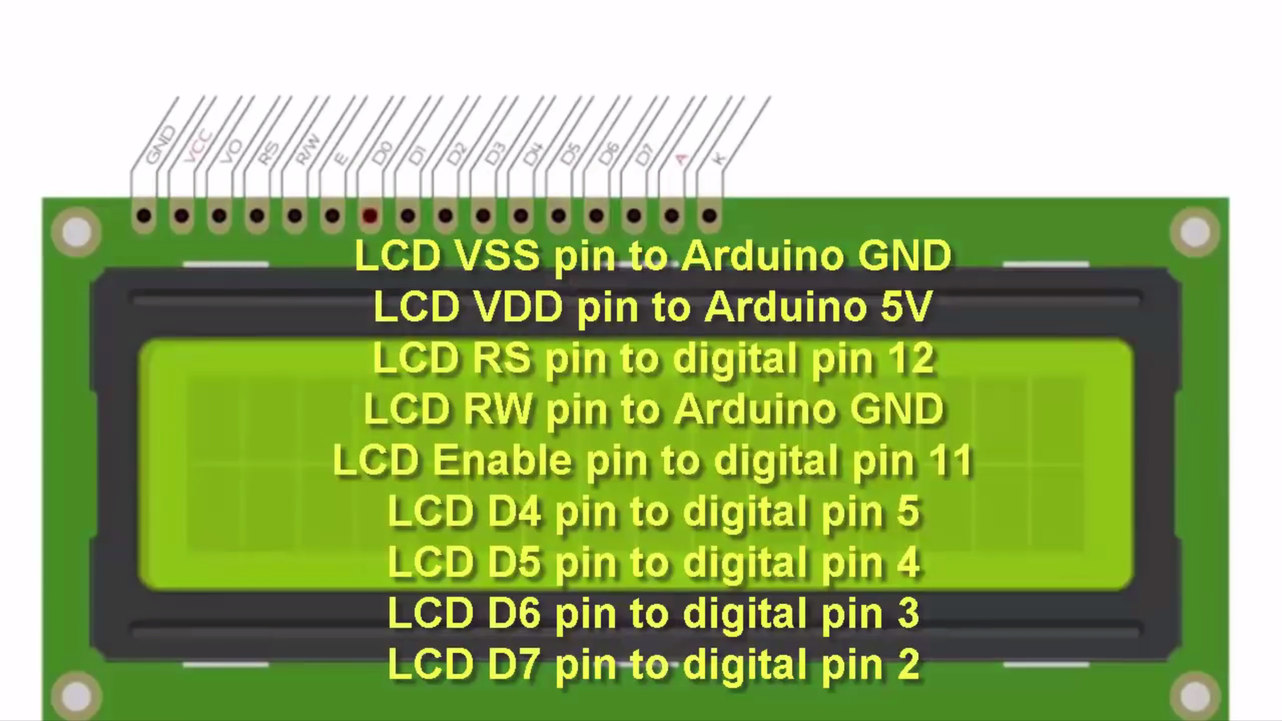
To wire your LCD screen to your board, connect the following pins:
LCD VSS pin to Arduino GND
LCD VDD pin to Arduino 5V
LCD RS pin to digital pin 12
LCD RW pin to Arduino GND
LCD Enable pin to digital pin 11
LCD D4 pin to digital pin 5
LCD D5 pin to digital pin 4
LCD D6 pin to digital pin 3
LCD D7 pin to digital pin 2
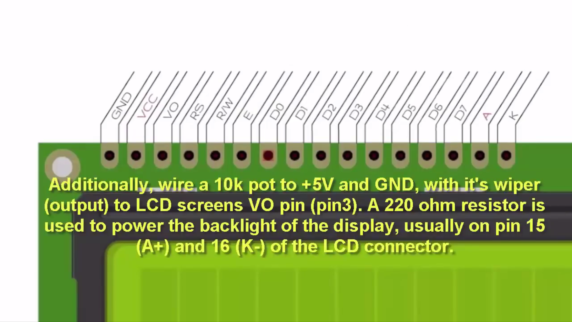
Additionally, wire a 10k pot to +5V and GND, with it's wiper (output) to LCD screens VO pin (pin3).
A 220 ohm resistor is used to power the backlight of the display, usually on pin 15 (A+) and 16 (K-) of the LCD connector.
Step 4: Programming

The process of controlling the display involves putting the data that form the image of what you want to display into the data registers, then putting instructions in the instruction register. The LiquidCrystal Library simplifies this for you so you don't need to know the low-level instructions.
The LiquidCrystal library allows you to control LCD displays that are compatible.
Step 5: If I Was Helpful


First of all, I would like to thank you for reading this guide ! I hope it helps you.
If you want to support me, you can subscribe my channel and watch my videos.


