

Introduction: Full Bridge Rectifier DIY


In this tutorial will be explained step by step the process of making a full bridge rectifier. One of the main advantages of this devices is the possibility of having a power supply for DC Voltage components from an AC Voltage source.
Step 1: Design of the Circuit


In this step, the design of the circuit will be presented. The required materials are:
- 127-24 VAC transformer (the central tap will be used in order to get only 12 Volts)
- Four diodes (1N4001)
- Capacitor (10uF)
- Push button
- Relay (THD-1201L)
- Potentiometer (10 Kohms)
- DC Voltage regulator of 5 Volts (7805)
- Two DC motors (12 Volts and 5 Volts)
- Wire (AWG 22)
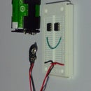
The two images show the wiring diagram for the circuit
Step 2: Getting DC Voltage for the Motors


The transformator will reduce the voltage. The input Voltage comes from the domestic supply (127 Volts). The voltage is reduce to 12 Volts. Still we have a AC voltage, and the motors will not work. The AV voltage has the form of a sine wave with positive and negative value. The diodes will inver the negative voltage into a positive one. The capacitor will produce a more uniform DC output voltage. The push button will activate or deactivate the voltage supply for the motors.
The rectified voltage (now 12 DC voltage) will be coupled with the relay, the potentiometer and the voltage regulator. The voltage regulator will supply the 5 Volts DC motor.
The Potentiometer will be coupled with the 12 Volts motor in order to control the on-off of the motor. The push button will be used as main switch.
Step 3: Reliable Power Supply
Know, can we build our own power supply for dc componets. While attaching electronics, extra attention should be paid, in order to supply more voltage that required for the electronics.


